IPoE RD-Based Stateful Redundancy for Subscriber Groups
Overview
Node outages and link failures that may occur on an access network can bring down the subscriber services. These network outages affect critical workloads and continuity of business. So, it is essential to set up a network that is resilient and responds quickly to the events and protects the network from outages.
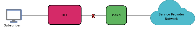
The following diagram represents a simple access network without redundancy.
IPoE RD-based Stateful Redundancy protects subscriber services from node or link outages. RD-based redundancy refers to a deployment that uses the Redundancy Daemon (RD), an application designed to manage redundancy deployment on the access side of the BNG, especially in topologies similar to Multi-Chassis LAG.
It provides mechanisms to enhance network resiliency that enables subscriber workloads to remain functional by ensuring a reliable switchover in the event of a node or link outage. With Redundancy, if one node goes down due to node or link failure, another node can automatically take over the services.
|
Understanding RD-Based Stateful Redundancy for IPoE
RBFS supports stateful redundancy and fault tolerance through two primary mechanisms:
-
Active-Active Redundancy
-
Active-Standby Redundancy
You can select the desired redundancy mechanism and configure the system accordingly to enable the feature. By default, the Active-Active (Standby-Forwarding) mode is enabled. If you prefer to use the Active-Standby Redundancy mode, select the Standby-Non-Forwarding option in the Platform Profile configuration. This is a one time configuration unless you choose to switch to the other Redundancy mode.
IPoE RD-based Stateful Redundancy is centered around subscriber groups, known as redundancy sessions. It protects subscriber groups using a two-node cluster model, either active-active or active-standby.
The following image illustrates two different redundancy mechanisms: Active-Active and Active-Standby. In Active-Active mode, both BNG nodes and LAGs forward traffic. In Active-Standby mode, only the active node and the LAG (between the OLT and the active node) handle traffic, while the standby node remains idle until a failover occurs.
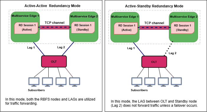
From the perspective of the OLT, there is only one LAG that is distributed across multiple BNGs. This means that the OLT sees one logical link, even though it is physically connected to two separate BNGs. But, in reality, this LAG spans two BNGs, indicating that the OLT is actually connected to two different devices.
Redundancy Session
Redundancy session is a replication mechanism that is used to pair Multiservice Edge nodes for redundancy. Redundancy allows grouping of subscribers, under a redundancy session and each redundancy session is represented by a redundancy session ID. Simply put, an redundancy session represents a redundancy group of subscribers. A redundancy session enables linking the LAG with that particular redundancy session (subscriber group). When you define a value for the redundancy session ID, this ID should be unique and the same for both redundancy pairs. When two nodes get the same session ID, they recognize each other as the peer nodes for a particular redundancy session (subscriber group). The TCP session establishment between the nodes occurs after the pairing with the redundancy session ID. Once the TCP session is established, the nodes use this channel for subscriber data mirroring and synchronization and for health status monitoring.
A Multiservice Edge chassis can contain multiple redundancy sessions. Multiple Multiservice Edge nodes can be active nodes for one or more subscriber groups (redundancy sessions) that serve the subscribers and they can, at the same time, be standby nodes for other subscriber groups.
One node, which is paired for redundancy, can perform subscriber services for more than one redundancy session (subscriber group). The peer node, which is identical to the first node, contains the same subscriber group (redundancy session) as a standby. And in the event that first node goes down due to any outage, the standby node can take over subscriber service for this redundancy session.
RD-based IPoE Stateful Redundancy allows running a redundancy session actively on one node and backing up the same redundancy session (subscriber group) on a different (standby) Multiservice Edge node. In IPoE redundancy, in fact, there is no active node or standby node. It is either an active subscriber group or standby subscriber group. A Multiservice Edge node can be active for a subscriber group and at the same time it can be a standby for a different subscriber group. You can configure a maximum number of 64 redundancy sessions (either active or standby) on a Multiservice Edge node.
Active-Active Redundancy
In the Active-Active Redundancy mode, both of the nodes and their associated LAGs are actively used for traffic forwarding. Both the nodes synchronize their subscriber state information in real-time. This ensures that all the LAG links towards the OLT are utilized for maximum resource efficiency.
If one node fails, the other node can immediately take over the responsibilities with minimal disruption, as it is already synchronized with the active node. This mechanism provides fast failover with minimal traffic disruption and ensures traffic flow.
Pinning or Assigning a Subscriber to a Link of a LAG
RBFS uses a pinning mechanism where the system assigns or 'pins' each subscriber to each of the LAG member links between active/standby nodes and the OLT.
Subscribers are assigned during session bringup to member links belonging to the access LAG on both of the nodes. They will be assigned either as locally pinned or remotely pinned. This ensures an equal distribution of subscribers across all member links.
Locally pinned: Refers to subscribers pinned to a member links of the LAG of the Active node.
Remotely pined: Refers to subscribers pinned to a member links of the LAG of the Standby node.
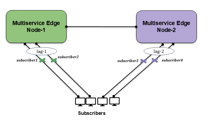
OLT is excluded from the diagram to simplify it and is not directly relevant to what is depicted.
The diagram illustrates the pinning mechanism, where Subscriber 1 is pinned to Link 1 of LAG 1, and Subscriber 2 is pinned to Link 2 of LAG 1. Similarly, Subscriber 3 is pinned to Link 1 of LAG 2, while Subscriber 4 is pinned to Link 2 of LAG 2.
| When a member link of the access LAG fails on either the active or standby device in the Active-Active Redundancy mode, the system retriggers the subscriber pinning process to maintain an equal distribution of subscribers across the access LAG member links. |
-
Locally pinned subscribers will be in 'established' state on the active node and in the standby state on the Standby node.
-
Remotely pinned subscribers will be in the 'established non-forwarding' state on the active node and in the 'standby-forwarding' state on the standby node.
Subscriber Pinned to Active Node
The following table provides the various subscriber state for the Active-Active Redundancy.
| Subscriber Pinning | State on Active Node | State on Standby Node |
|---|---|---|
Pinned to Active Node |
Established |
Standby |
Pinned to Standby Node |
Established Non-Forwarding |
Standby-Forwarding |
The following example shows the IPoE subscribers pinned to different LAGs and their states.
supervisor@rtbrick.net: cfg> show subscriber
Subscriber-Id           Interface         VLAN       Type    State
1369375761697341460     lag-1             1001:1001  IPoE    ESTABLISHED
1369375761697341463     lag-1             1001:1004  IPoE    ESTABLISHED_NO_FWD
2522297266304188429     lag-11            2001:1001  IPoE    STANDBY
2522297266304188430     lag-11            2001:1002  IPoE    STANDBY_FWD
The subscriber ID 1369375761697341460 is pinned to 'lag-1' and is in established state on Active node. The subscriber ID 1369375761697341463 is pinned to 'lag-1' is in a established-non-forwarding mode on the active node. The subscriber ID 2522297266304188429 is pinned to 'lag-11' and is in standby mode on the Standby node. The subscriber ID 2522297266304188430 is pinned to 'lag-11' and is in standby-forwarding mode on the Standby node.
Active-Standby Redundancy
In the active-standby node cluster, the active node (for a redundancy session) performs subscriber services. The standby device mirrors concurrent subscriber state data from the active peer (for that redundancy session). Both the nodes, paired for redundancy, keep sending 'keepalive' messages to each other to check the health status.
In this mode, the standby RBFS node does not forward traffic while the active RBFS node is functioning. The standby node stays synchronized with the active node by maintaining up-to-date routing tables, configurations, and session data, but it does not perform any traffic forwarding. If the active node fails, the standby node will take over its role and start forwarding traffic.
Active node handles all subscriber traffic and control plane processing. In this model, the standby LAG is not utilized for traffic unless a failover occurs.
IP Address Pool Management for Redundancy
There is no synchronization between local IP address pools, so an IP address on one BNG will not be reflected in the other BNG’s IP address pool.
So, it is highly recommended to use RADIUS for IP address management. If local pools are used, they must be configured with disjoint address ranges across all nodes. While an IP address assigned by a pool on the active BNG can be transferred to the standby BNG during failover, the local pools are not synchronized.
Subscriber Services on Redundancy
Subscriber services refer to the various features that can be applied to subscribers, such as access control lists, HTTP redirect, lawful interception, CGNAT, IGMP, and Accounting. When deploying these services in a redundancy setup, special handling is required. The behavior of each service varies depending on whether the Redundancy mode is active-active or active-standby.
The following table provides information about the various services supported on Active-Active Redundancy and Active-Standby Redundancy.
| Service | Active-Active | Active-Standby |
|---|---|---|
Accounting |
Supported: Both BNGs perform accounting and RADIUS aggregates counters. |
Supported: Only the active BNG performs accounting. |
Lawful Interception |
Supported: LI must be enabled on both BNGs. |
Supported: LI happens in active BNG and the data is synced to standby BNG. |
HTTP Redirect |
Supported: Enabled on both BNGs. |
Supported: Enabled only in active BNG and synced to standby BNG. |
CGNAT |
Unsupported |
Unsupported |
Subscriber ACL |
Supported: ACLs are programmed on both BNGs. |
Supported: ACLs programmed only in active BNG and synced to standby BNG. |
ADF (Application Detection and Filtering) |
Unsupported |
Unsupported |
Dynamic QoS Profiles |
Supported: QoS profile changes via CoA sync on both BNGs. |
Supported: QoS profile changes via CoA sync to standby BNG. |
Dynamic QoS Parameters |
Unsupported |
Unsupported |
IGMP (Multicast Services) |
Unsupported |
Unsupported |
Inter-BNG Connectivity
Multiservice Edge platforms, deployed as redundant pairs, are connected through a Redundancy session to maintain state consistency. This Redundancy session uses a TCP connection between the active and standby BNG nodes over an IP/MPLS link. TCP connection can be formed using the directly connected interfaces on the two Multiservice Edge nodes through an IP/MPLS path. The session between the Multiservice Edge nodes is used to send 'keepalive' messages and mirror data in real time. Both the active and standby BNG nodes advertise subscriber routes using the same metric.
RBFS Redundancy mechanism provides several advantages. Downstream traffic arrives either on the active or standby BNG since both advertise subscriber routes with the same metric. If the traffic arrives on the active BNG, it is delivered directly to the subscriber. If the traffic arrives at the standby BNG, it redirects the traffic to the active BNG over the inter-BNG connection.
Another advantage is that the Multiservice Edge nodes do not withdraw or re-advertise subscriber routes if an access link goes down. A link-down event on the access side does not trigger any change in route advertisements on the core side. When an access link fails, the traffic redirection from the impacted BNG to the other (redundant) BNG occurs locally and quickly without re-advertising or withdrawing routes in the core network.
In the event of a redundancy session failure, 'keepalive' messages can no longer be exchanged between the peer nodes. After the hold timer expires, the affected node transitions to a standalone operational state. All previously synchronized subscriber session data between the nodes becomes invalid.
IPoE RD-based Stateful Redundancy Architecture
The following architectural diagram provides a high-level view of RD-based IPoE stateful redundancy mode. It shows two RBFS nodes, paired for redundancy, deployed in an active-standby node cluster, with their interfaces are connected with an RD TCP connection. These peer nodes use the RD TCP connection for sending 'keepalive' messages and data mirroring for subscriber state synchronization.
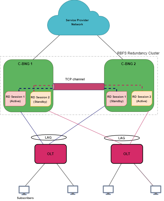
Both of the nodes are connected to an access device (OLT device in this scenario) on one end from where it receives subscriber traffic and sends traffic. The nodes are also connected to the core network on the other end.
The node 'Multiservice Edge 1' is in active state and performs subscriber services for the 'Session 1' (redundancy subscriber group). 'Session 1' is also mirrored in the Multiservice Edge 2 in standby mode. The standby device mirrors concurrent subscriber state data for 'Session 1' from the active peer. If an active node goes down due to any reason, the peer node detects the outage and uses mirrored 'Session 1' to perform subscriber services.
One Multiservice Edge node acts as an active node for one or more sessions (subscriber redundancy groups) and as a standby Multiservice Edge for other subscriber redundancy groups at the same time. The following diagram illustrates the scenario.
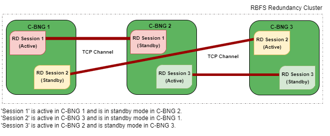
IPoE RD-based Stateful Redundancy can mitigate the following types of failures:
-
Link failure Between Active RBFS Node and Access Node (OLT, DSLAM or MSAN)
-
Node Outage
Redundancy for Node Outage
A node outage, which can bring down the subscriber services, can occur due to many reasons on a network. IPoE RD-based Stateful Redundancy helps to minimize the impact and reduce interruptions and downtime by providing a resilient system. In the event of a node outage, IPoE RD-based Stateful Redundancy triggers switchover in which the standby node takes over from the active node with very minimal impact on the subscriber services.
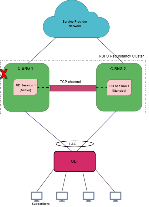
The diagram shows multiservice-edge1 as an active node serving subscribers and multiservice-edge2 stays as a standby. When an active node goes down, the standby node detects the same and takes over from the active RBFS node. In a node outage scenario, the node becomes unresponsive and cannot maintain communication with its peer node the RD TCP link.
Redundancy for Link Failure
In IPoE RD-based Stateful Redundancy, Link Aggregation combines multiple physical links into a single logical link. If a member link, which is part of a LAG, goes down, the LAG fails. The diagram shows the 'multiservice-edge1' and 'multiservice-edge2' deployed in redundancy mode and is connected to the access device with LAGs. When the LAG between 'multiservice-edge1' and the access node goes down, the 'multiservice-edge1', which is running 'Session 1', becomes inactive for the subscriber group. So the 'multiservice-edge2', which is the standby for 'Session 1', detects the failure of 'multiservice-edge1' and starts performing subscriber services for 'Session 1' by providing a quick recovery from the disruption.
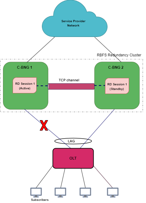
In this link or LAG failure scenario, multiservice-edge1 is in a healthy state, only the LAG interface went down. It cannot perform subscriber services for the particular redundancy session. However, it can keep communication with its peer node as the RD TCP channel.
Node States in Redundancy
In IPoE RD-based Stateful redundancy, Multiservice Edge nodes have different states for various redundancy sessions. Typically, IPoE Stateful redundancy nodes encounter the following states for redundancy sessions:
Active: All subscribers are served by active node in the RBFS active-standby node cluster. One node which is active for a redundancy session can be a standby node for a different session. Nodes, that are paired for redundancy, send 'keepalive' messages to each other and also synchronize all subscriber state data with the peer node. The priority values that you specify for the redundancy nodes determine the roles of active and standby. The node that receives the higher priority value for the session ID assumes the role of active for that subscriber group. To set one device as 'active', you must specify higher priority value for the redundancy session for that node.
Standby: Standby node is identical with the active node and synchronizes subscriber data concurrently from peer node. It keeps communication with the peer node to monitor node health status using 'keepalive' messages. The node that gets the lower priority value for the redundancy session ID assumes the role of standby. Standby node for a subscriber group does not perform any subscriber services for that group unless or until the active node encounters an outage.
Down: When a node becomes inactive due to an outage, it is considered as 'down'. In the event of a node outage, it is completely down and cannot perform subscriber services and any communication with its peer node. But in the case of a LAG (between the node and access node) failure, the node cannot perform subscriber services, but it can communicate with the peer node through the RD TCP connection. So that the subscriber state synchronization occurs without any interruption.
Stand Alone: When the active node goes down, the switchover occurs and standby takes over the subscriber service. In this scenario, the serving node is in 'stand alone' state (for that redundancy session) as it has no peer node for redundancy.
Revert or Rollback Active-Standby Redundancy Mode
In IPoE RD-based Stateful Redundancy, after a node or link failure and the subsequent switchover, the standby takes over and continues the subscriber service for that subscriber group even after the other node (previously active) recovers from the failure. There is no automated rollback or revert to the previously active router. However, administrators can perform a manual switchover for the Active-Standby Redundancy mode.
Monitoring Node Health Status
The RBFS nodes, which have switchover capacities, monitor each other for the health status. IPoE RD-based Stateful Redundancy uses 'keepalive' messages that check on the health of the RBFS nodes. Both of the devices send 'keepalive' messages to each other in every five seconds. One node can detect a failure if it does not receive 'keepalive' messages for a period of 20 seconds from the other node.
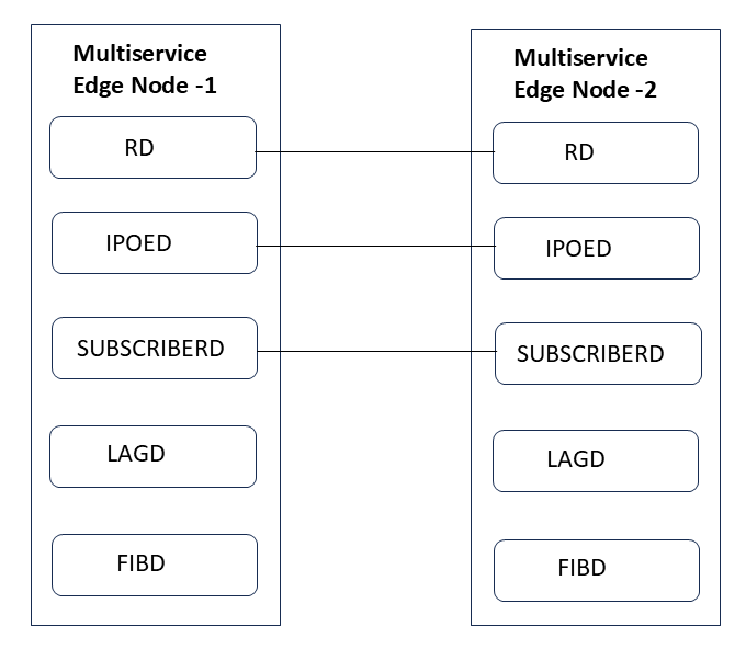
Redundancy Clients
There are multiple RBFS daemons that participate in providing redundancy. They include redundancy daemon, (rd), LAG daemon (lagd), interface daemon (ifmd), subscriber daemon (subscriberd), IPoE daemon (ipoed) and forwarding daemon (fibd). These daemons, which perform various roles, are known as redundancy clients.
Redundancy in DHCP Relay Mode
RBFS supports RD-based Stateful Redundancy for IPoE in both DHCPv4 and DHCPv6 relay modes. RBFS can maintain synchronized IPoE session states across redundant Multiservice Edge nodes operating in 'relay' mode.
| In DHCP Relay mode, source address configured for DHCP server on both of the Multiservice Edge nodes should be different, and the proxy-ARP "any" should be enabled. |
Redundancy Daemon
Redundancy Daemon is responsible for establishing high-availability connections. It monitors the ecosystem and detects any outages that may happen on the network. It assigns the roles of active or standby to the nodes depending on the priority configured on the node. The daemon triggers a switchover to the standby node if a failure occurs. It responds to the failure events which are reported locally by daemons who are the redundancy clients. It also reconciles the data after switchover from the node that went down.
Supported Hardware Platforms
Currently, RBFS can be deployed in redundancy mode using the RBFS Multiservice Edge switches. Multiservice Edge software provides complete BNG functionalities on a single compact hardware switch. Both the Active-Active Redundancy and Active-Standby Redundancy modes are supported in the following hardware platforms:
-
UfiSpace S9600-72XC: The UfiSpace S9600-72XC is a multi-function, disaggregated white box aggregation routing platform that is equipped with Broadcom’s Qumran2c chipset. It features 64x25GE and 8x100GE high-speed ports with a switching capacity of up to 2.4Tbs.
-
Edgecore AGR420: AGR420 is a high performance 25GbE aggregation router that consists of fixed 64 x 10G/25G SFP28, 8 x 100GE QSFP28 and 2 x 100G QSFP-DD network interface configurations.
Only Active-Standby Mode is supported on the following platforms:
-
Edgecore CSR440
-
UfiSpace S9510-28DC
IPoE RD-Based Stateful Redundancy Requirements
The following are the requirements for setting up Redundancy.
-
Ensure that both of the platform devices, on which RBFS software runs, must be the same model.
-
Ensure that the devices should run the same version of RBFS software. RBFS software 23.2.1 and later versions support Active-Standby redundancy mode and 25.1.1 and later versions support Active-Active Redundancy mode.
-
NTP must be configured on both devices to match the timestamps.