OSPF Overview
OSPF (Open Shortest Path First) is an Interior Gateway Protocol that distributes routing information within a single Autonomous System (AS) in an IP network. OSPF is a link-state routing protocol that uses link-state information to form a routing table and exchange the routing information with the neighbors.
RtBrick FullStack (RBFS) supports OSPF version 2 (OSPFv2) and OSPF version 3 (OSPFv3), including authentication, LDP-IGP sync, and redistribution policy. RBFS does not support OSPFv3 Virtual Link.
OSPF routers flood LSAs (link-state advertisements) to all other routers in an autonomous system. Routers generate routing tables using the information received from the LSAs and calculate the best path to other routers in the network. OSPF uses the Dijkstra (Shortest Path First) algorithm to calculate the best path.
LSAs contain local state information such as interfaces and the reachability of neighbors. Other routers, which receive this information as LSAs, build their LSDB (link-state database) using this information. In an OSPF network, all routers build and maintain information about the topology of that network.
OSPFv3
OSPF Version 3 (OSPFv3) is a modified version of OSPF and it provides support for the OSPF routing protocol within an IPv6 network. As such, it provides support for IPv6 addresses and prefixes. It retains most of the structure and functions in OSPFv2 (for IPv4) with a few changes.
OSPFv3 differs from OSPFv2 in the following ways:
-
OSPFv3 runs on IPv6, which is based on links rather than network segments
-
OSPFv3 does not depend on IP addresses
-
OSPFv3 packets and the LSA format have the following changes:
-
OSPFv3 router LSAs and network LSAs do not contain IP addresses, which are advertised by Type 8 LSAs and Type 9 LSAs
-
-
In OSPFv3, information about the flooding scope is added in the LSA Type field
-
OSPFv3 stores or floods unidentified packets, whereas OSPFv2 discards
-
-
OSPFv3 supports multi-process on a link with instance ID
-
OSPFv3 uses IPv6 link-local addresses for forwarding
OSPFv3 Instance ID
One of the advancements of OSPFv3 over OSPFv2 is the use of the instance ID. This instance ID is an 8-bit field within the OSPFv3 header.
The original intent for the instance ID was to support multiple instances of OSPFv3 to run on the same interface. In this way, you can manipulate which routers on a particular segment are allowed to form adjacencies. You could use an instance number of 0 through 255 to distinguish between the different OSPFv3 instances.
However, within RFC 5838, the instance ID was re-purposed to be used to support address families (AFs) with OSPFv3. The default instance of 0 is used if no other instance is defined. However, specific ranges of the instance ID map to specific AFs. According to the RFC, these ranges are:
-
Instance ID 0 to 31 — IPv6 unicast AF
-
Instance ID 32 to 63 — IPv6 multicast AF
-
Instance ID 64 to 95 — IPv4 unicast AF
-
Instance ID 96 to 127 — IPv4 multicast AF
-
Instance ID 128 to 255 — Unassigned
When using IPv4 unicast or IPv6 unicast, the allowed values for the command are between 0 and 31.
| RBFS only supports IPv6 unicast addresses ranging from 0 to 31. |
Understanding OSPF Areas
OSPF allows for a logical partition of the autonomous system by dividing it into areas. This logical partitioning helps to limit the flooding of link-state updates within an area.
An OSPF Autonomous System can be maintained as a single-area network or can be divided as a multi-area network. In a single area AS, the topology provides link-state information of routers in the entire autonomous system.
In a multi-area AS, the topology provides the link-state information of routers belonging to that particular area, not about routers in other areas in the autonomous system. Within an area, all OSPF routers maintain separate databases which are identical.
In a multi-area OSPF network, all areas are connected to the backbone area, known as Area 0.
Backbone Area
The backbone area, also known as Area 0, is connected to all other areas in an OSPF network. The backbone area, which acts as a central point of communication, receives LSAs from other areas and disseminates the same to other areas.
Area Border Router
Routers that connect one or more areas with the backbone area are called Area Border Router (ABR). One interface of the ABR is connected to the backbone, while other interfaces are connected to other areas. ABRs, which belong to multiple areas in an OSPF network, maintain separate LSDBs for each area that they are connected to.
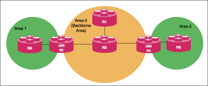
The following OSPF architectural diagram shows a simple OSPF network that is divided into areas. Area 1 and Area 2 are connected to the backbone area (Area 0) through the ABRs. Area 1 and Area 2 are not directly connected. They receive link state advertisements from each other from Area 0 which acts as the central point of communication for all other areas.
Autonomous System Boundary Router
ASBR (Autonomous System Boundary Router) serves as a gateway router to the OSPF autonomous system. ASBR can operate multiple protocols and work with other autonomous system routers that run other interior gateway protocols such as EIGRP, IS-IS, i-BGP, and so on. ASBR can import and translate different protocol routes into OSPF through the redistribution mechanism.
OSPF DR and BDR Election
An OSPF network chooses one router as a Designated Router (DR) and another as a Backup Designated Router (BDR) for a broadcast network.
DR acts as a central point of communication by receiving and distributing topology information. BDR takes over the role of DR if the DR fails. Routers in an OSPF network do not directly exchange routing information with each other. Instead, every router in the network updates routing information only with DR and BDR. DR, in turn, distributes the topology information with all other routers. This mechanism reduces network traffic significantly. OSPF chooses one router as DR and another router as BDR based on the following criteria:
-
The router with the highest priority value becomes the designated router and the router with the second highest priority value becomes the BDR. You can define the priority values for routers during the interface configuration.
-
If multiple routers have the same highest priority value, then the router with the highest router ID is elected as DR and the router with the second highest router ID value becomes the BDR.
You can choose a priority value from the range 0 - 255. Routers with the priority value '0' do not participate in the DR or BDR election.
Supported OSPF Standards
RBFS supports the following RFCs, which define standards for OSPFv2 and OSPFv3.
-
RFC 2328, OSPF Version 2
-
RFC 5340, OSPF for IPv6
-
RFC 5709, OSPFv2 HMAC-SHA Cryptographic Authentication
-
RFC 7166, Supporting Authentication Trailer for OSPFv3
-
RFC 8665, OSPF Extensions for Segment Routing
-
RFC 8666, OSPFv3 Extensions for Segment Routing
| RFC and draft compliance are partial except as specified. |