RD-Based Stateless Redundancy for PPPoE Subscribers
Overview
RBFS supports RD-based Redundancy for PPPoE subscribers to maintain service continuity during node or link failures. The Redundancy is based on a deterministic active-standby BNG architecture, where only one BNG node actively establishes, maintains and terminates subscriber sessions. The standby BNG node remains idle and ready to take over if there is a failure on the active BNG node.
Subscriber traffic is managed exclusively by the active BNG node and the standby node continuously monitor the health of the active node. PPPoE Redundancy does not synchronize subscriber session state between the active and standby nodes. When a failure occurs, the standby node promotes itself to the active role based on health monitoring mechanism.
When an outage occurs on the active node, all existing PPPoE sessions on that node are terminated. Affected subscribers are required to re-initiate PPPoE discovery and authentication. Subscriber services are restored by establishing new PPPoE sessions on the standby node (standalone) that becomes active. Subscribers, re-onboarded on the new standby node, are assigned a new IP address from its local pool. As a result, downstream traffic is redirected to the new active node without any route advertisements or withdrawals.
|
Understanding RD-Based Stateless Redundancy for PPPoE Subscribers
Inter-BNG Connectivity and Redundancy Session
The BNG nodes configured as a redundancy pair maintain a redundancy session over an TCP connection through an IP/MPLS link. TCP connection can be formed using the directly connected interfaces or via an IP/MPLS path through core network. This communication channel is used by the standby node to continuously monitor the health state of the active node. The redundancy session remains established as long as the TCP connection is available. The session between the nodes is used to send 'keepalive' messages to check the node health. In the event of a failure on the active node, the standby node detects the failure through this channel and initiates the failover.
Every redundancy session is represented by a redundancy session ID. When you define a value for the redundancy session ID, this ID should be unique within the redundancy group or domain and must be configured with the same value on both nodes (active and standby) participating in that redundancy session. When two nodes get the same session ID, they recognize each other as the peer nodes for a particular redundancy session.
From the perspective of the OLT, there is only one active-standby LAG that is distributed across multiple BNGs. This means that the OLT sees one logical link, even though it is physically connected to two separate BNGs.
PPPoE Stateless Redundancy Architecture
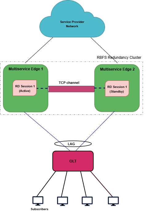
The following architectural diagram provides a high-level view of PPPoE redundancy mode. It shows two RBFS nodes, paired for redundancy, deployed in an active-standby node cluster, with their interfaces are connected with an TCP connection.
Both nodes are connected to an OLT device on southbound (access) side, through which they receive and forward subscriber traffic. On the northbound side, the nodes are connected to the core network for upstream and downstream communication.
PPPoE Redundancy can mitigate the following types of failures:
-
Link failure Between Active RBFS Node and Access Node (OLT, DSLAM or MSAN)
-
Active Node Outage
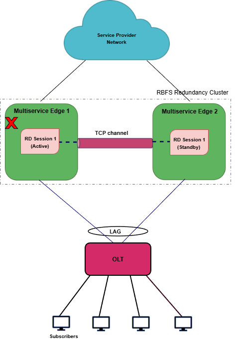
Redundancy for Node Outage
When the active BNG node fails, the standby node detects the failure through health-state monitoring maintained by the redundancy session. The standby node then transitions to standalone mode, activates the LAG, and re-onboards subscribers. The following diagram illustrates a node outage scenario.
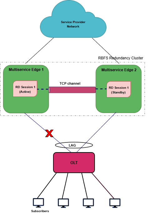
Redundancy for Link Failure
A LAG is considered down when the number of member links falls below the configured minimum link threshold. When this occurs, the affected node can no longer serve subscriber traffic. The standby node detects the failure through the TCP connection and initiates failover by re-onboarding subscribers and establishing new sessions. The following illustration depicts a LAG failure scenario in which the active LAG between the 'multiservice-edge1' node and the OLT device goes down.
Node States in PPPoE Redundancy
Multiservice Edge nodes have different states for various redundancy sessions.
Active: All subscribers are served by active node in the RBFS active-standby node cluster. One node which is active for a redundancy session can be a standby node for a different session. The priority values that you specify for the redundancy nodes determine the roles of active and standby. The node that receives the higher priority value for the session ID assumes the role of active for that subscriber group.
Standby: Standby node keeps communication with the active BNG node to monitor node health status using the 'keepalive' messages. The node that gets the lower priority value for the redundancy session ID assumes the role of standby. Standby node for a subscriber group does not perform any subscriber services for that group unless or until the active node encounters an outage.
Down: When a node becomes inactive due to an outage, it is considered as 'down'. In the event of a node outage, it is completely down and cannot perform subscriber services and any communication with its peer node. But in the case of a LAG (between the node and access node) failure, the node cannot perform subscriber services, but it can communicate with the peer node through the RD TCP connection.
Stand Alone: When the active node goes down, the switchover occurs and standby takes over the subscriber service. In this scenario, the serving node is in 'stand alone' state (for that redundancy session) as it has no peer node for redundancy.
Supported Hardware Platforms
Currently, RBFS can be deployed in redundancy mode for the PPPoE subscribers using the following RBFS Multiservice Edge platforms.
-
UfiSpace S9600-72XC
-
UfiSpace S9600-102XC
-
UfiSpace S9510-28DC
-
Edgecore CSR440 (AS7535-28XB)
Additional Requirements for PPPoE Redundancy
The following are additional requirements which must be met before setting up Redundancy.
-
Ensure that both of the platform devices, on which RBFS software runs, must be the same model.
-
Ensure that the devices should run the same version of RBFS software. RBFS software 25.4.1 and later versions support Active-Standby redundancy mode for PPPoE subscribers.
-
NTP must be configured on both devices to match the timestamps.