Interface Configuration
Module Introduction
Before you start the hands-on part of this module, you should load the appropriate configuration and verify that the testbed is up and running by executing the corresponding robot file:
student@tour:~/trainings_resources/robot$ robot interfaces/interfaces_setup.robotIn order to get a better understanding, the lab setup is shown in the picture below.
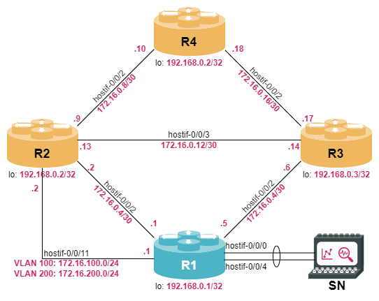
Interface Types and Naming Conventions
RBFS supports various types of interfaces:
-
Physical Interfaces (short IFP), typically represent the physical ports of a hardware switch. On the physical interface level, you can configure various parameters associated with Layer 1 of the ISO/OSI reference model.
-
Host Interfaces represent Linux virtual ethernet (veth) interfaces which connect an LXC container with the Linux host OS. These interfaces are used with virtual switch devices and topologies.
-
Loopback interface is typically used to represent and identify a device itself. Loopback interfaces are preferred because they do not depend on the status of a physical port, and will always be up.
-
Logical Interfaces (IFL) can be created on top of physical interfaces, host interfaces or loopback interfaces. A logical interface is associated with the Layer 2 operation, such as VLAN handling, as well as Layer 3 parameters like IP addresses on interface units, and assign interface units to routing instances.
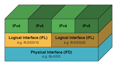
RBFS interface numbers match the port numbers on the switch faceplate. An interface is named in the ifp-<chassis-ID>/<front-panel-block-number>/<port> format. For example, ifp-0/0/1. Virtual interfaces follow the same structure, for example lo-0/0/1 or hostif-0/0/1.
Logical interfaces are numbered: ifl-<Node ID>/<Chip ID>/<Port ID>/<Unit ID>, for example ifl-0/0/1/1.
cfg> show interface summary
Interface                Admin    Link     Oper          IPv4 Address             IPv6 Address
hostif-0/0/0             Up       Up       Up
hostif-0/0/1             Up       Up       Up
hostif-0/0/2             Up       Up       Up
hostif-0/0/4             Up       Up       Up
hostif-0/0/11            Up       Up       Up
Physical Interface Configuration
The physical properties of a physical interface (IFP) as well as a host interface (hostif) are configured using the syntax set interface <ifname> <attribute> <value>. With these commands you can set speed, autonegotiation or link-training, which only apply to certain physical interface types. In addition, you can always set the admin-status to up or down to enable or disable the interface and set a description.
An overview of physical interfaces present in the system is available with the show interface physical command:
cfg> show interface physical
Interface          Admin   Link    Oper    MAC Address          Speed  Duplex  Uptime
hostif-0/0/0       Up      Up      Up      7a:77:1f:c0:00:00    -      -       Tue Mar 14 12:57:08 GMT +0000 2023
hostif-0/0/1       Up      Up      Up      7a:77:1f:c0:00:01    -      -       Wed Mar 15 07:35:12 GMT +0000 2023
hostif-0/0/2       Up      Up      Up      7a:77:1f:c0:00:02    -      -       Wed Mar 15 07:35:12 GMT +0000 2023
hostif-0/0/4       Up      Up      Up      7a:77:1f:c0:00:04    -      -       Wed Mar 15 07:35:12 GMT +0000 2023
hostif-0/0/11 Up Up Up 7a:77:1f:c0:00:0b - - Wed Mar 15 07:35:12 GMT +0000 2023You have already seen how to use the show lldp neighbor command to find out what is connected to each link.
Use this information to set interface descriptions to 'Link to <Neighbor>, <Port>' for all known neighbors.
Click to reveal the answer
First, let’s run show lldp neighbor to find out what is connected to each interface:
cfg> show lldp neighbor
Neighbor name      Status  Remote port ID     Local port ID      Neighbor MAC address  Last received     Last sent
R2                 Up      hostif-0/0/1       hostif-0/0/1       7a:78:e5:00:00:00     0:00:28 ago       0:00:28 ago
R2                 Up      hostif-0/0/11      hostif-0/0/11      7a:78:e5:00:00:00     0:00:28 ago       0:00:28 ago
R3                 Up      hostif-0/0/2       hostif-0/0/2       7a:0a:71:01:00:00     0:00:00 ago       0:00:28 ago
With this information, we can set the interface descriptions:
set interface hostif-0/0/1 description "Link to R2, hostif-0/0/1"
set interface hostif-0/0/2 description "Link to R3, hostif-0/0/2"
set interface hostif-0/0/11 description "Link to R2, hostif-0/0/11"
commit
Finally, we can verify the effect of our change with show interface description
cfg> show interface description
Interface          Admin    Link     Oper     Description
hostif-0/0/1       Up       Up       Up       Link to R2, hostif-0/0/1
hostif-0/0/2       Up       Up       Up       Link to R3, hostif-0/0/2
hostif-0/0/11 Up Up Up Link to R2, hostif-0/0/11| Always set an interface description as it helps troubleshooting. In case active transport equipment is used between two switches, include references to the transport equipment as well. |
The interface hostif-0/0/0 and hostif-0/0/4 are not used at the moment. Shut down the interfaces by setting the admin-status to down, then verify with show interface physical
Click to reveal the answer
set interface hostif-0/0/0 admin-status down
set interface hostif-0/0/4 admin-status down
commit
We can now verify the administrative state of the interface:
cfg> show interface physical
Interface              Admin   Link    Oper    Damp      MAC Address          Speed  Duplex  Uptime
hostif-0/0/0           Down    Down    Down    stable    7a:56:0c:c0:00:00    -      -       never
hostif-0/0/1           Up      Up      Up      stable    7a:56:0c:c0:00:01    -      -       Fri Jun 26 15:47:05 GMT +0000 2026
hostif-0/0/2           Up      Up      Up      stable    7a:56:0c:c0:00:02    -      -       Fri Jun 26 15:47:05 GMT +0000 2026
hostif-0/0/4           Down    Down    Down    stable    7a:56:0c:c0:00:04    -      -       never
hostif-0/0/11 Up Up Up stable 7a:56:0c:c0:00:0b - - Fri Jun 26 15:47:05 GMT +0000 2026| For a complete list of interface configuration options, refer to the Interfaces Overview. |
Logical Interface Configuration
The logical interface properties are configured using the syntax set interface <ifname> unit <unit-id> …. An important logical interface property is the instance name, because every logical interface is tied to exactly one routing instance.
If the interface supports additional structure, e.g., VLANs, the associated parameters are set on the same configuration hierarchy.
| If you do not have VLAN tags, there is usually only one logical interface per physical interface and it is best practice to use unit 0 for the logical interface. |
The IPv4 addresses of a logical interface are set using the set interface <ifname> unit <unit-id> address ipv4 <address> command.
If you need to run IPv6 on a logical unit, first you need to enable it with set interface <ifname> unit <unit-id> ipv6-admin-status up, then you can set the actual addresses with set interface <ifname> unit <unit-id> address ipv6 <address>.
Configure the interfaces on your system according to the IP addresses in the table below. Once you have completed the task, you should be able to ping the remote interface.
| Interface Name | IPv4 Address | IPv6 Address |
|---|---|---|
hostif-0/0/1 |
172.16.0.1/30 |
fc00:c0a8:0:1:172:16:0:1/64 |
hostif-0/0/2 |
172.16.0.5/30 |
fc00:c0a8:0:3:172:16:0:5/64 |
lo-0/0/0/0 |
192.168.0.1/32 |
fc00:c0a8::192:168:0:1/128 |
| You need to enable the corresponding address families in the default routing instance. |
Remember that to enable IPv6 on a logical unit you need to set its ipv6-admin-status to up, in addition to configuring its IPv6 addresses.
|
Click to reveal the answer
set interface hostif-0/0/1 unit 0 ipv6-admin-status up
set interface hostif-0/0/1 unit 0 address ipv4 172.16.0.1/30
set interface hostif-0/0/1 unit 0 address ipv6 fc00:c0a8:0:1:172:16:0:1/64
set interface hostif-0/0/2 unit 0 ipv6-admin-status up
set interface hostif-0/0/2 unit 0 address ipv4 172.16.0.5/30
set interface hostif-0/0/2 unit 0 address ipv6 fc00:c0a8:0:3:172:16:0:5/64
set interface lo-0/0/0 unit 0 ipv6-admin-status up
set interface lo-0/0/0 unit 0 address ipv4 192.168.0.1/32
set interface lo-0/0/0 unit 0 address ipv6 fc00:c0a8::192:168:0:1/128
set instance default address-family ipv4 unicast
set instance default address-family ipv6 unicast
commit
We can now verify our configuration with show interface address
cfg> show interface address
Interface              Instance            IPv4 Address             IPv4 Primary   IPv6 Address
lo-0/0/0/0             default             192.168.0.1/32           True           fc00:c0a8::192:168:0:1/128
hostif-0/0/1/0         default             172.16.0.1/30            True           fc00:c0a8:0:1:172:16:0:1/64
                                           -                                       fe80::7856:cff:fec0:1/64
hostif-0/0/2/0         default             172.16.0.5/30            True           fc00:c0a8:0:3:172:16:0:5/64
                                           -                                       fe80::7856:cff:fec0:2/64
RBFS supports commands like ping and traceroute to verify connectivity at the IP layer. Both of these commands send ICMP Echo Request packets to a destination which answers with ICMP Echo Reply packets.
After successfully configuring the IP addresses on the interface, you should test the connectivity with the ping command. The remote destination has an IP address directly succeeding the local IP address. What additional options does the ping command provide?
Click to reveal the answer
cfg> ping 172.16.0.2 count 1
68 bytes from 172.16.0.2: icmp_seq=1 ttl=64 time=9.7706 ms
Statistics: 1 sent, 1 received, 0% packet loss
cfg> ping fc00:c0a8:0:1:172:16:0:2 size 1000 count 1
1008 bytes from fc00:c0a8:0:1:172:16:0:2: icmp_seq=1 ttl=64 time=10.5281 ms
Statistics: 1 sent, 1 received, 0% packet loss
cfg>
The ping command allows to set
-
the number of ICMP Echo Requests to be sent with
count -
the packet size of the ICMP Echo Request with
size -
the routing instance which sources the pakcets with
instance(default: "default") -
the ToS field of the ICMP packet with
tos
Configuring VLAN Interfaces
In general, interfaces can have multiple logical units. For RBFS to decide, which unit to send and receive packets, the unit must be associated with layer-2 framing structure called VLAN ID. RBFS supports single-tagged VLANs (vlan) according to IEEE 802.1Q as well as double-tagged VLANs (vlan and inner-vlan) according to IEEE 802.1ad.
Configure the interface hostif-0/0/11 with two units using VLAN-tagging:
-
unit 100: VLAN-ID 100 and IP address of 172.16.100.1/24
-
unit 200: S-VLAN 200, C-VLAN 10 and IP address of 172.16.200.1/24
Verify the connectivity by pinging the remote endpoints with addresses respectively 172.16.100.2 and 172.16.200.2.
Click to reveal the answer
set interface hostif-0/0/11 unit 100 vlan 100
set interface hostif-0/0/11 unit 100 address ipv4 172.16.100.1/24
set interface hostif-0/0/11 unit 200 vlan 200
set interface hostif-0/0/11 unit 200 inner-vlan 10
set interface hostif-0/0/11 unit 200 address ipv4 172.16.200.1/24
commit
We can now ping through the logical interfaces we just configured
cfg> ping 172.16.100.2 count 3
ping to 172.16.100.2 60 byte packets
68 bytes from 172.16.100.2: icmp_seq=1 ttl=64 time=10.00 ms
68 bytes from 172.16.100.2: icmp_seq=2 ttl=64 time=10.00 ms
68 bytes from 172.16.100.2: icmp_seq=3 ttl=64 time=9.99 ms
--- 172.16.100.2 ping statistics ---
3 sent, 3 received, 0 errors, 0.00% loss, time 3009.41 ms
rtt min/avg/max/mdev = 9.99/10.00/10.00/0.00 ms

cfg> ping 172.16.200.2 count 3
ping to 172.16.200.2 60 byte packets
68 bytes from 172.16.200.2: icmp_seq=1 ttl=64 time=9.38 ms
68 bytes from 172.16.200.2: icmp_seq=2 ttl=64 time=10.03 ms
68 bytes from 172.16.200.2: icmp_seq=3 ttl=64 time=10.02 ms
--- 172.16.200.2 ping statistics ---
3 sent, 3 received, 0 errors, 0.00% loss, time 3015.35 ms
rtt min/avg/max/mdev = 9.38/9.81/10.03/0.30 ms
Configuring Link Aggregation
Link aggregation (sometimes called link bundling) is a method used to combine multiple physical network links into a single logical link. One of the primary benefits of link aggregation is the ability to increase the overall bandwidth between two devices. Another aspect is fault tolerance, i.e., if one link in the aggregated group fails, the remaining links can continue to carry traffic, reducing the impact of a link failure.
The IEEE 802.3ad standard defines a specific protocol for link aggregation called Link Aggregation Control Protocol (LACP). LACP allows network devices, such as switches, to negotiate the bundling of links and manage the distribution of traffic across those links.
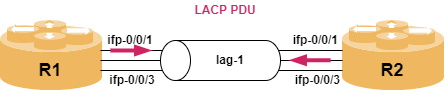
With LACP, the links that are bundled together are called a Link Aggregation Group (LAG) which is represented by a single logical interface. LACP is used to negotiate certain parameters between the corresponding nodes by exchanging control packets (LACP PDUs) to determine which links should be part of the bundle. There are two different LACP modes named active and passive. In active mode, a device actively sends LACP packets to negotiate and form a LAG. In passive mode, the device waits for the other end to initiate the negotiation. LACP supports load-balancing, i.e., traffic is distributed across the bundled links. If one or more links in the LAG fail, LACP can detect the failure and redistribute traffic across the remaining active links. You can define a minimum number of links that need to be active for the LAG to be active.
In RBFS, the link aggregation interface is defined using the set link-aggregation interface <lag-name> command hierarchy. The supported LAG interface names in RBFS are lag-1 to lag-99.
Set the administrative status of interfaces hostif-0/0/0 and hostif-0/0/4 to up.
Use set link-aggregation interface <name> … commands to configure a link-aggregation group named lag-1 with mode lacp, minimum-link-count 2, and the two interfaces hostif-0/0/0 and hostif-0/0/4 as members, both in active mode.
Set the description of the link-aggregation interface to "Link Aggregation to SN", commit and verify that the link bundle comes up with the show lag and show lag details commands.
You can use the question mark (?) to show the available configuration options.
|
Click to reveal the answer
set interface hostif-0/0/0 admin-status up
set interface hostif-0/0/4 admin-status up
set link-aggregation interface lag-1 description "Link Aggregation to SN"
set link-aggregation interface lag-1 mode lacp
set link-aggregation interface lag-1 minimum-link-count 2
set link-aggregation interface lag-1 member-interface hostif-0/0/0 lacp-mode active
set link-aggregation interface lag-1 member-interface hostif-0/0/4 lacp-mode active
commit
Once we have configured the LAG interface, we can verify that it is working:
cfg> show lag
LAG Interface     Speed   Status      Member Interface  Actor System ID     Partner System ID   Actor Key   Partner Key
lag-1             -       Resolved    hostif-0/0/0      7a:56:0c:01:00:81   92:10:3d:e7:3c:36   10          15
                                      hostif-0/0/4      7a:56:0c:01:00:81   92:10:3d:e7:3c:36   10          15

cfg> show lag lag-1 detail
LAG interface name: lag-1
  Status             : Resolved
  Speed              : -
  Minimum link count : 2
  Mode               : lacp
    Member interface name: hostif-0/0/0
      Actor system ID   : 7a:56:0c:01:00:81
      Actor key         : 10
      Partner system ID : 92:10:3d:e7:3c:36
      Partner key       : 15
    Member interface name: hostif-0/0/4
      Actor system ID   : 7a:56:0c:01:00:81
      Actor key         : 10
      Partner system ID : 92:10:3d:e7:3c:36
      Partner key       : 15
From the output above we can see that there is a new lag bundle consisting of two physical interfaces. In addition, we can see our own LACP actor system ID as well as the peer’s system ID.
Now let’s check the impact of the minimum-link configuration by disabling one of the member interfaces:
cfg> set interface hostif-0/0/4 admin-status down
cfg> commit
Remember we configured the link-aggregation interfaces for a minimum-link value of 2. Let’s check what happened to the link bundle after we disabled a link:
cfg> show lag lag-1 detail
LAG interface name: lag-1
  Status             : Unresolved (Minimum link count error)
  Speed              : -
  Minimum link count : 2
  Mode               : lacp
    Member interface name: hostif-0/0/0
      Actor system ID   : 7a:56:0c:01:00:81
      Actor key         : 10
      Partner system ID : 92:10:3d:e7:3c:36
      Partner key       : 15
    Member interface name: hostif-0/0/4
As expected, the whole lag goes down as a result of disabling one member link as the required number of active links is no longer met.
We can now rollback our changes, to bring up again interface hostif-0/0/4, and with it the whole bundle:
rollback 1
commit
Verify that the bundle is back up:
cfg> show lag lag-1
LAG Interface     Speed   Status      Member Interface  Actor System ID     Partner System ID   Actor Key   Partner Key
lag-1             -       Resolved    hostif-0/0/0      7a:56:0c:01:00:81   92:10:3d:e7:3c:36   10          15
                                      hostif-0/0/4      7a:56:0c:01:00:81   92:10:3d:e7:3c:36   10          15
The link aggregation group can be used like any other Ethernet link. Thus, we can configure on it a logical unit with an IP address and use it as a normal interface using the set interface <lag-name> unit <unit> address … command.
On interface lag-1, configure unit 0 with an ipv4 address of 172.16.99.1/24 and assign it to the default instance. Then, use the show interface address command to check that the address has been correctly assigned; finally, verify that you can ping through the lag interface the destination IP address of 172.16.99.2.
Click to reveal the answer
set interface lag-1 unit 0 instance default
set interface lag-1 unit 0 address ipv4 172.16.99.1/24
commit
Verify that the address has been assigned, and ping the remote side:
cfg> show interface address lag-1/0
Interface              Instance            IPv4 Address             IPv4 Primary   IPv6 Address
lag-1/0                default             172.16.99.1/24           True
cfg> ping 172.16.99.2 count 3
68 bytes from 172.16.99.2: icmp_seq=1 ttl=64 time=1.4045 ms
68 bytes from 172.16.99.2: icmp_seq=2 ttl=64 time=.2370 ms
68 bytes from 172.16.99.2: icmp_seq=3 ttl=64 time=4.5594 ms
Statistics: 3 sent, 3 received, 0% packet loss
Monitoring Interfaces
There are various commands that allow you to monitor the interface operations and help you troubleshoot issue. First of all, it is always useful to display the interface statistics, that provides some information about packets being sent and received:
op> show interface hostif-0/0/1/0 statistics
Logical Interface:  hostif-0/0/1/0
  VPP statistics:
    Counter              Unit      Count
    Rx                   packets   14
                         bytes     11444
    Tx                   packets   734
                         bytes     72064
    IPv4                 packets   9
    IPv6                 packets   0
    MPLS                 packets   0
    Punt                 packets   0
    Drops                packets   5
    Rx Miss              packets   0
    Rx Error             packets   0
    Rx No Buff           packets   0
    Tx Error             packets   0
The interface statistics can be reset with the command clear interface statistics <ifp|ifl>.
Clear the interface statistics on interface hostif-0/0/1/0. Afterwards sent some ICMP Echo Requests (ping) to your neighbor. How does the interface statistics change? Also try some ping options like count, size.
Click to reveal the answer
op> clear  interface statistics hostif-0/0/1/0
op> ping 172.16.0.2 count 10 size 1200
1208 bytes from 172.16.0.2: icmp_seq=1 ttl=64 time=6.9126 ms
<...>
Statistics: 10 sent, 10 received, 0% packet loss
op> show interface hostif-0/0/1/0 statistics
Logical Interface:  hostif-0/0/1/0
  VPP statistics:
    Counter              Unit      Count
    Rx                   packets   10
                         bytes     12080
    Tx                   packets   10
                         bytes     12080
    IPv4                 packets   10
    IPv6                 packets   0
    MPLS                 packets   0
    Punt                 packets   0
    Drops                packets   0
    Rx Miss              packets   0
    Rx Error             packets   0
    Rx No Buff           packets   0
    Tx Error             packets   0