Layer-2 Tunneling Protocol (L2TP)
Module Introduction
Before you start the hands-on part of this module, you should load the appropriate configuration and verify that the testbed is up and running by executing the corresponding robot file:
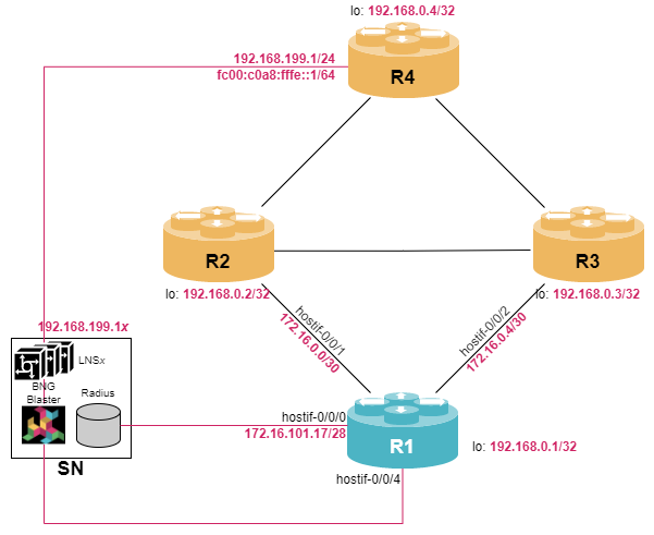
student@tour:~/trainings_resources/robot$ robot l2tp/l2tp_setup.robotIn order to get a better understanding, the lab setup is shown in the picture below.
| Configuring PPPoE subscriber profile is a prerequisite for L2TP being used. In case you are not familiar with PPPoE, we recommend to study module PPPoE Subscribers first. |
Layer-2 Tunneling Protocol (L2TP) Overview
With PPPoE, a subscriber runs a point-to-point connection (PPP session) to a Broadband Network Gateway (BNG) across that PPPoE connection. In most cases, the PPPoE termination point and PPP session endpoint resides on the same physical device. However, tunneling protocols, such as Layer-2 Tunneling Protocol version 2 (L2TPv2) provide a dynamic mechanism for extending PPP by allowing the PPPoE and PPP endpoints to reside on different devices that are interconnected by an IP network.
There are various networking scenarios where it makes sense to deploy L2TP tunnels, e.g.,
-
L2TP can be used to create isolated tunnels for different wholesale clients enabling broadband providers to offer access infrastructure to wholesale partners
-
L2TP tunnels can carry Ethernet frames effectively over IP-based networks allowing to extend Layer-2 networks
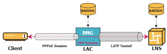
The BNG now acts as a L2TP access concentrator (LAC), which physically terminates the PPPoE session and tunnels the PPP packets across an IP network to the L2TP network server (LNS). The LNS then terminates the logical PPP connection.
| RBFS does currently not support the LNS functionality. |
L2TP Tunnel Setup
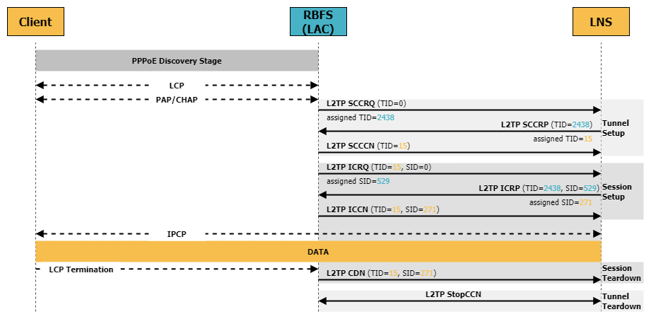
In order to setup, maintain, and teardown L2TP tunnels and sessions between LAC and LNS, L2TP uses the control connection
-
The LAC sends a Start-Control-Connection-Request (SCCRQ) message to the LNS. This message initiates the negotiation of various parameters and includes an assigned tunnel ID which will be used to identify the L2TP tunnel.
-
Upon receiving the SCCRQ message, the LNS responds with a Start-Control-Connection-Reply (SCCRP) message. This message acknowledges the request and contains the remote tunnel ID as well as an assigned tunnel ID for the local side.
-
Once both the LAC and LNS have exchanged SCCRQ and SCCRP messages and negotiated the necessary parameters, the control connection is established by sending a Start-Control-Connection-Connected (SCCCN) message.
The negotiated tunnel IDs are used to identify the L2TP on both sides.
L2TP Session Setup
With the control connection established, the LAC and LNS can now use control messages to establish, maintain and teardown L2TP sessions:
-
The LAC sends an Incoming-Call-Request (ICRQ) to the LNS to initiate the establishment of a session within a tunnel. This session initiation is triggered by an PPP LCP negotiation issued by a subscriber. Note, that a tunnel can carry multiple sessions, so once a subscriber initiates a PPP session, the tunnel may or may not already established. The ICRQ contains an assigned session ID to identify the subscriber session within the tunnel.
-
The LNS responds with an Incoming-Call-Reply (ICRP) negotiating session parameters including the session ID to identify the remote side of the session and advertise an assigned session ID to identify the local side of the connection.
-
Once LAC and LNS have exchanged ICRQ and ICRP message and agreed on session parameters, the session is established by sending an Incoming-Call-Connected (ICCN).
The LAC is now able to forward traffic from the subscriber to the LNS through the L2TP tunnel.
L2TP Session and Tunnel Teardown
A session can be terminated by sending a Call-Disconnect-Notify (CDN). This message can be sent by either side, but most often is triggered by a PPP LCP Termination Request.
When the control connection needs to be terminated, either the LAC or LNS can initiate the process by sending a Stop-Control-Connection-Notification (StopCCN).
L2TP LAC Configuration
In most real-world deployments, L2TP is used with RADIUS authentication. So, in case the PPPoE configuration is already in place as described in module PPPoE Subscribers, the L2TP configuration is pretty simply: just turn on l2tp in the access-profile using the set access access-profile <profile_name> protocol l2tp command. This is the only mandatory command.
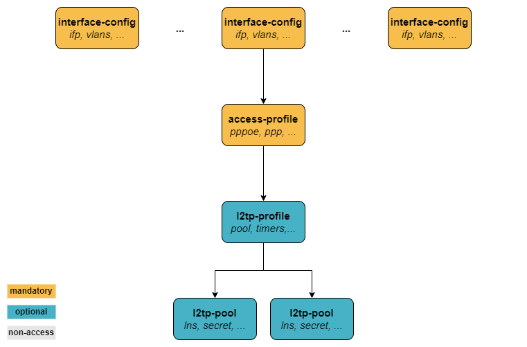
However, for a better understanding of L2TP, we first want to configure an L2TP profile in this section. As already mentioned, this step is optional.
The Layer 2 Tunnel Protocol (L2TPv2) pool configuration allows to define local sets of possible L2TP LNS server endpoints using the set access l2tp-pool <l2tp_poolname> syntax. The pool defines LNS IP addresses, the local IP address as well as a shared secret key.
Configure a L2TP pool named LNSSERVER defining two LNS devices (LNS1 with IP address of 192.168.199.11 and LNS2 with IP address of 192.168.199.12). The shared secret key should be test123. Used the IP address associated with the loopback address as client IP address.
Click to reveal the answer
cfg> set access l2tp-pool LNSSERVER R1 LNS1
cfg> set access l2tp-pool LNSSERVER R1 LNS1 client-ipv4 192.168.0.1
cfg> set access l2tp-pool LNSSERVER R1 LNS1 server-ipv4 192.168.199.11
cfg> set access l2tp-pool LNSSERVER R1 LNS1 secret-plain-text test123
cfg> set access l2tp-pool LNSSERVER R1 LNS2
cfg> set access l2tp-pool LNSSERVER R1 LNS2 client-ipv4 192.168.0.1
cfg> set access l2tp-pool LNSSERVER R1 LNS2 server-ipv4 192.168.199.12
cfg> set access l2tp-pool LNSSERVER R1 LNS2 secret-plain-text test123
cfg> commit
Next, we will define a L2TP profile using the set access l2tp-profile <l2tp_profilename> command. The profile can be used to define various parameters, e.g., the LNS selection algorithm and tunnel and session timers.
Configure a L2TP profile named L2TP_LAC and assign the pool LNSSERVER to it. Also limit the number of sessions to 100.
Click to reveal the answer
cfg> set access l2tp-profile L2TP_LAC
cfg> set access l2tp-profile L2TP_LAC session-limit 100
cfg> set access l2tp-profile L2TP_LAC pool-name LNSSERVER
cfg> set access l2tp-profile L2TP_LAC client-name R1
cfg> set access l2tp-profile L2TP_LAC client-ipv4 192.168.0.1
cfg> commit
Finally, we need to bind the L2TP profile to the existing PPPoE access profile.
Enable l2tp protocol in the PPPOE_ACCESS profile and assign the L2TP profile L2TP_LAC to it.
Click to reveal the answer
cfg> set access access-profile PPPOE_ACCESS protocol l2tp tunnel-profile L2TP_LAC
cfg> commit
So far, we have not used RADIUS in this section, thus we need to create a local user and assign the L2TP pool to it in order to verify our setup.
Configure a local user account named user1@l2tp via the set access user-profile command. The secret should be set to test and the L2TP pool set to LNSSERVER.
Click to reveal the answer
cfg> set access user-profile user1@l2tp
cfg> set access user-profile user1@l2tp password-encrypted-text $243a1341f44f54888cdd385b9f40513f1
cfg> set access user-profile user1@l2tp tunnel-type L2TP
cfg> set access user-profile user1@l2tp l2tp-pool-name LNSSERVER
cfg> commit
Monitoring L2TP Tunnels and Sessions
In order to see some useful CLI output, we need a test subscriber to establish a session with our RBFS device. The virtual lab environment comes with a service node (SN) that has BNG Blaster pre-installed - an open-source test tool that allows to emulate PPPoE subscribers as well as L2TP LNS devices. A short introduction to the BNG Blaster can be found in the Supplementary Material in section BNG Blaster. For more details refer to the BNG Blaster Documentation.
Now let’s open another terminal, log into the service node and start the BNG Blaster:
student@tour:~$ rtb-ssh SN
Logging into SN as supervisor ...
<...>
supervisor@SN:~ $ sudo bngblaster -C subscriber_l2tp.json -c 1
[sudo] password for supervisor:
Aug 10 07:27:46.781017 Resolve network interfaces
Aug 10 07:27:46.781143 All network interfaces resolved
Aug 10 07:27:51.833953 ALL SESSIONS ESTABLISHED
Aug 10 07:27:53.210033 ALL SESSION TRAFFIC FLOWS VERIFIED
The password for user supervisor is simply supervisor on the virtual training environment.
|
Once the message ALL SESSIONS ESTABLISHED appears on the screen, you can switch to the RBFS CLI and execute some monitoring commands. The BNG Blaster session is terminated using Ctrl+c. The switch -c 1 instructs the BNG Blaster to establish one session. You can vary the number of session count, however, as we have only one user profile configured, all other sessions will fail to establish. You can also execute the BNG Blaster with the option -I which start the interactive mode.
We can verify that one subscriber session is active. You can use either the show subscriber or the show pppoe session or the show l2tp subscriber command to verify the status of the subscriber sessions.
cfg> show subscriber
Subscriber-Id          Interface        VLAN      Type   State
72339069014638727      hostif-0/0/4     128:101   L2TP   ESTABLISHED

cfg> show pppoe session
Subscriber-Id          Interface        VLAN      MAC               State
72339069014638727      hostif-0/0/4     128:101   02:00:00:00:00:01 TUNNELLED

cfg> show l2tp subscriber
Subscriber-Id          State
72339069014638727      ESTABLISHED
Note, that the subscriber ID is the same in all outputs and that the status of the PPPoE session is TUNNELED indicating that L2TP is used to tunnel the traffic to an LNS.
Let’s get some more information on the L2TP tunnel. Therefore, we have to extract the tunnel ID (TID) and session ID (SID) that identify the subscriber.
cfg> show l2tp subscriber 72339069014638727
Subscriber-Id: 72339069014638727
    State: ESTABLISHED
    Local TID: 16553
    Local SID: 11013
    Peer TID: 1
    Peer SID: 1
    Call Serial Number: 41
    TX Speed: 1000000000 bps
    RX Speed: 1000000000 bps
    CSUN: disabled

cfg> show l2tp session
Subscriber-Id          Local TID Local SID State
72339069014638727          16553     11013 ESTABLISHED
The show l2tp tunnel command provides some useful information about the L2TP tunnels, e.g., status and peer IP address:
cfg> show l2tp tunnel
Role Local TID Peer TID State        Peer Name
LAC      12087        0 INACTIVE     LNS2
LAC      16553        1 ESTABLISHED  LNS1
cfg> show l2tp tunnel 16553
Local TID: 16553 Peer TID: 1
    State: ESTABLISHED
    State Changed: Thu Aug 10 07:27:47 GMT +0000 2023
    Role: LAC
    Preference: 0
    Session Limit: 100
    Hello Interval: 30 seconds
    Access-Profile: PPPOE_ACCESS
    L2TP-Profile: L2TP_LAC
    CSUN: disabled
    Tunnel-Client-Auth-ID: R1           (1)
    Tunnel-Server-Auth-ID: LNS1         (2)
    Local Tunnel Endpoint:
        Instance: default
        IPv4 Address: 192.168.0.1       (1)
        Hostname: R1
        Receive Window: 8
    Peer Tunnel Endpoint:
        IPv4 Address: 192.168.199.11    (2)
        Hostname: LNS1
        Vendor: bngblaster
        Firmware: 1
        Framing: SYNC,ASYNC
        Bearer: DIGITAL
Receive Window: 16| 1 | Client (LAC) ID and IP address |
| 2 | Server (LNS) ID and IP address from L2TP pool |
The command provides two tunnels, one established and one inactive. The reason for having two tunnels listed is that our L2TP pool contains two LNS definitions. The command clear l2tp tunnel can be used to clean up all inactive tunnels if needed:
cfg> clear l2tp tunnel delete-inactive all
1 inactive L2TP tunnel deleted
cfg> show l2tp tunnel
Role Local TID Peer TID State        Peer Name
LAC      16553        1 ESTABLISHED  LNS1
In case you have multiple subscribers, you can also view the distribution of sessions among the L2TP tunnels which is also useful to monitor the load:
cfg> show l2tp tunnel sessions
Role Local TID Peer TID State        Preference Sessions Established Peer Name
LAC       5217        2 ESTABLISHED       10000        2           2 LNS4
LAC      20855        1 ESTABLISHED       10000        1           1 LNS3
When L2TP sessions or tunnels are experiencing connectivity issues, it is often useful to see the history of their disconnections. RBFS provides the history knob for the show l2tp tunnel | session command to provide the termination code for further investigation:
cfg> show l2tp tunnel history
Sequence Local TID Peer TID Timestamp                            Terminate Code
       1     21416        1 Tue Aug 08 11:25:05 GMT +0000 2023   StopCCN Received (Requester is being shut down)
       2     13629        2 Tue Aug 08 11:25:05 GMT +0000 2023   StopCCN Received (Requester is being shut down)
       3     21416        2 Tue Aug 08 11:31:47 GMT +0000 2023   StopCCN Received (Requester is being shut down)
       4     13629        1 Tue Aug 08 11:31:47 GMT +0000 2023   StopCCN Received (Requester is being shut down)
<...>

cfg> show l2tp session history
Subscriber-Id          Local TID Local SID Terminate Code
72339069014638594          23087     21933 L2TP CDN Request
72339069014638595          23087     64846 L2TP CDN Request
<...>
RADIUS Authentication
The most scalable user management solution is using RADIUS, which allows each subscriber to be assigned individual tunnel and session parameters without defining a large number of L2TP pools and L2TP profiles on the local system. The RADIUS VSAs that are supported by RBFS include Tunnel-Client-Endpoint, Tunnel-Server-Endpoint, Tunnel-Password, and Tunnel-Preference as described in RFC 2868.
| RBFS does not support FQDN format for IP addresses and no Tunnel-Medium-Type other than IPv4. |
Modify the AAA access profile to use RADIUS authentication instead of LOCAL authentication.
Click to reveal the answer
cfg> set access aaa-profile PPPOE_AUTH aaa-radius-profile MYRADIUS
cfg> set access aaa-profile PPPOE_AUTH authentication order RADIUS
cfg> commit
Now, let’s check that RADIUS authentication is working. Therefore, we log into the service node SN once again and restart BNG Blaster with session count of five. As a result, we can verify that all L2TP sessions are established:
cfg> show l2tp session
Subscriber-Id          Local TID Local SID State
72339069014638740          31590     30869 ESTABLISHED
72339069014638737          23948     22648 ESTABLISHED
72339069014638738          23948     26321 ESTABLISHED
72339069014638736          11769     39483 ESTABLISHED
72339069014638739          11769      2174 ESTABLISHED

cfg> show l2tp tunnel sessions
Role Local TID Peer TID State        Preference Sessions Established Peer Name
LAC      11769        2 ESTABLISHED       10000        2           2 LNS3
LAC      23948        1 ESTABLISHED       10000        2           2 LNS4
LAC      31590        3 ESTABLISHED       10000        1           1 LNS5
We also notice, that the peer names are provided by the RADIUS server as we have only defined LNS1 and LNS2 in our local L2TP pool.