MPLS Basic Concepts
Module Introduction
This module deals with the basic concepts and terms of MPLS. There are no exercises in this module.
MPLS Overview
In traditional IP networks, each router performs an IP lookup in its routing table to determine the next hop router and then forwards the packet to that next hop router. This procedure is repeated at every single node along the path to the destination, i.e., each router needs to inspect the IP packet header and makes its own forwarding decision (hop-by-hop routing). As a routing table may contain multiple potential matches for a particular IP address, the router needs to perform a longest prefix match (LPM) to select the best entry.
Multiprotocol Label Switching (MPLS) was originally developed in the late 1990s to speed up the processing of IP packets. Early network processors consisted of FPGAs rather than ASICs and the processing speed depended significantly on the length of the lookup fields. Therefore, using a fixed-length header was more appealing than using a variable length IP header. In addition, MPLS uses an exact match instead of a longest prefix match which is more efficient. In MPLS networks only the first router performs a full IP routing lookup. In contrast to forwarding the packet on a hop-by-hop basis, it determines a pre-defined path to the final device which allows subsequent routers to skip the longest prefix lookup.
Although ASICs have evolved and eliminated the performance issues, MPLS is still widely deployed today due to the addition of many useful features, notably
-
virtualization of infrastructure allowing to implement different services across a shared packet switched network such as Layer-3 and Layer-2 Virtual Private Networks (VPNs)
-
ability to control how traffic is forwarded in order to manage capacities and priorities (traffic engineering)
-
improvement of network resiliency and reliability by mechanisms such as fast reroute
Building Blocks
Label Switching Routers
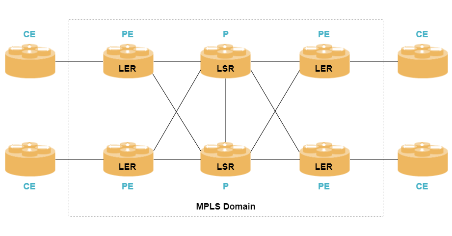
An MPLS domain is a network that consists of devices running MPLS. There are three different types of routers:
-
Label Switching Router (LSR) is a device that performs forwarding of MPLS packets. An LSR is usually a transit node within the MPLS domain node and sometimes also called a core router or a Provider (P) router in VPN context.
-
Label Edge Router (LER) is a LSR that connects an MPLS domain with a network outside of the MPLS domain. An LER that receives packets from a CE router is called an ingress LER, while an LER that sends packets to a CE device is called a egress LER.
The terms ingress and egress are used in respect of a specific traffic flow. In VPN terminology, a LER is called a Provider Edge (PE) router.
-
The MPLS specification has no special term for a router outside of the MPLS domain. In VPN context, they are called Customer Edge (CE) device.
A CE device can be part of another MPLS domain.
FECs and MPLS Labels
When a packet that enters an MPLS domain, it will be associated with a Forwarding Equivalence Class (FEC). The FEC is an abstract term for a set of packets that are handled identically within the MPLS network. In the simplest case, a FEC can correspond to an IP prefix in the routing table, i.e., two packets sharing the same longest prefix match belong to the same FEC. However, FECs can reflect other properties as well, for instance, quality-of-service. Two packets with the same IP destination but different QoS requirements will belong to two different FECs.
| Packets which belong to the same FEC will be handled equally, i.e., they share the same QoS treatment, the same path to the destination, etc. |
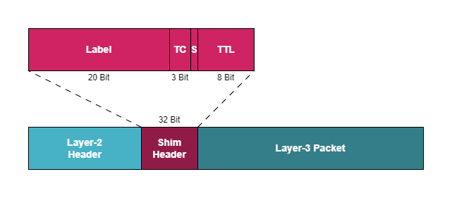
Once an ingress LER has received a packet and determined the corresponding FEC, it will encapsulate the packet into MPLS packets and forwarded through the MPLS domain to a remote PE router. MPLS packets use an MPLS header (also called shim header) which is inserted after the Layer-2 header (most commonly Ethernet header) and in front of the Layer-3 header (e.g., IPv4 or IPv6 header). The MPLS header has a length of 32 bits and consists of four fields:
-
MPLS label is a 20 bit identifier used for MPLS forwarding decisions
-
Traffic Class (TC) is a 3 bit field used to carry traffic class information. Note, that this field was originally called the experimental (EXP) field.
-
Bottom of Stack (S) bit
-
Time to Live (TTL) field which is 8 bit and used for loop avoidance similar to the IP TTL field
| A packet can have more than one MPLS header. This is called label stacking and the BoS bit indicates if there is another MPLS header or not. |
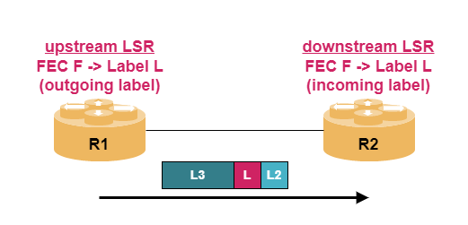
An MPLS router allocates a unique MPLS label that represents a FEC. The mapping between an MPLS label and a FEC is called label binding. For distribution of label bindings, it is important to understand the terms upstream and downstream. Consider two routers R1 and R2, then R1 is called the upstream node with respect to the FEC if it is closer to the ingress LER than R2. The router R2 is called downstream with respect to the FEC. MPLS packets are forwarded from the upstream node to the downstream node.
|
To enable processing of MPLS frames on a logical unit, ensure the configuration |
Label Operations
There are three fundamental MPLS packet operations:
-
push: The ingress PE router maps the FEC to a next hop and pushes an MPLS header containing an MPLS label to the packet.
-
swap: The P router - sometimes called transit LSR - swaps the label, i.e., it replaces the label of a packet to another label and forwards it to the next hop LSR.
-
pop: The top-most label of the label stack is removed. This operation is usually done by the egress LER.
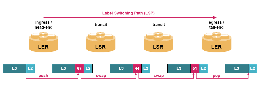
The path from an ingress LER via multiple transit LSRs towards an egress LER is called a Label Switching Path (LSP).
|
A Label Switched Path (LSP) is unidirectional from ingress (head-end) to egress (tail-end). For bidirectional traffic, you always need two LSPs which may or may not follow the same path in opposite directions. |
Note that routers along an LSP are unaware of the service offered at the PE routers. P routers only forward traffic based on MPLS labels thus removing a lot of state information from the P routers.
Penultimate Hop Popping (PHP)
An egress LER must remove (pop) the labels from an MPLS packet and afterwards perform a lookup on the remaining packet to determine how to forward the packet, i.e., it might be necessary to touch the packet twice. In order to optimize packet handling, the next-to-last LSR can remove the top-most label and egress LER can perform a normal packet lookup on the remaining packet. This mechanism is called penultimate hop popping (PHP).
But how does a LSR know that it is the next-to-last router? For PHP to work, the egress LER assigns a special purpose label called implicit NULL label with the well-define value of 3 to the FEC.
A drawback of using implicit NULL label is that there is no label on the last link of the MPLS network, i.e., QoS handling can only be based on IP packet header information. The egress LER can also assign an explicit NULL to a FEC which allows to carry the MPLS traffic class on the link.
| There are two flavors of explicit NULL labels: the IPv4 explicit NULL (label value 0) and the IPv6 explicit NULL (label value 2). |
MPLS Control Plane
Every MPLS node must run a routing protocol to exchange routing information with other MPLS nodes and populate an IP routing table. However, the routing table is not used for packet forwarding but for creating label bindings. In addition, a MPLS node must be able to distribute these label binding information to other MPLS nodes, especially the upstream nodes for a particular FEC. There are multiple options available:
-
Resource Reservation Protocol (RSVP)
-
Border Gateway Protocol (BGP)
MPLS control plane protocols can be classified based on certain properties:
-
Label retention mode specifies whether a router maintains a label binding learned from a neighbor or not. In conservative label retention mode, only those label bindings are kept that are used to forward packets (i.e., received from next hop along the shortest path). In liberal label retention mode, all label bindings are kept regardless of its use. Liberal retention allows to react faster to routing changes as the label bindings already exist.
-
Label advertisement mode describes whether the router advertises its label bindings to all neighbors (downstream unsolicited) or only to those routers that explicitly ask for label bindings (downstream on demand)
-
Label distribution control mode defines which router has control over the label allocation. In ordered mode, a router allocates a label for a FEC and advertises the label bindings only if it has received a label binding from the next hop router while in independent mode, the router performs allocation and distribution independently from its neighbors.