PPPoE Subscribers
Module Introduction
Before you start the hands-on part of this module, you should load the appropriate configuration and verify that the testbed is up and running by executing the corresponding robot file:
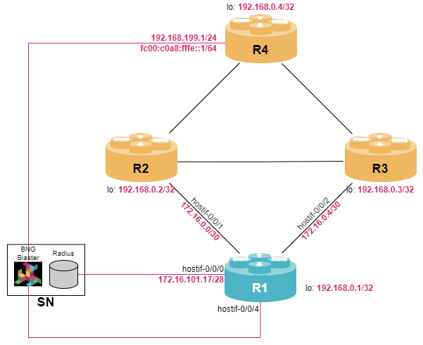
student@tour:~/trainings_resources/robot$ robot pppoe/pppoe_setup.robotIn order to get a better understanding, the lab setup is shown in the picture below.
PPPoE Overview
Point-to-Point Protocol (PPP) over Ethernet (PPPoE) is a networking protocol that allows the encapsulation of Point-to-Point Protocol (PPP) frames inside Ethernet frames. It is commonly used to establish a direct connection between a residential gateway and an Broadband Network Gateway (BNG) over an Ethernet aggregation network providing broadband access (e.g., DSL).
The main purpose of PPPoE is to facilitate the authentication of users and provide dynamic allocation of IP addresses. PPPoE session establishment and teardown can be broken into the following steps:
-
PPPoE discovery stage
-
PPPoE session stage
-
LCP negotiation
-
IPCP negotiation
-
Data traffic
-
LCP termination
-
-
PPPoE termination stage
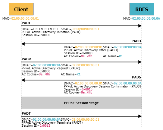
PPPoE Discovery Stage
-
When a user’s device initiates a connection, it sends a PPPoE discovery frame called PPPoE Active Discovery Initiation (PADI) as a broadcast to all devices on the local network, seeking a PPPoE server.
-
The BNG acts as a PPPoE server and replies to the PADI with a PPPoE Active Discovery Offer (PADO) frame including access concentrator name and other relevant parameters.
-
The user’s device then sends a PPPoE Active Discovery Request (PADR) frame to the BNG it wants to connect to.
-
The BNG acknowledges this request with a PPPoE Active Discovery Session-confirmation (PADS) frame.
LCP and IPCP
Once the PPPoE session is established, the client device initiates the PPP connection. The Link Control Protocol (LCP) is used to negotiate link parameters, e.g., maximum transmission unit (MTU), which determines the largest size of a data packet that can be transmitted over the link without fragmentation, and authentication type. LCP uses Configuration Request messages to suggest a setup o parameters and the peer responds with Configuration Acknowledge messages to accept these parameters.
If authentication is required, the devices use LCP to agree on an authentication method to verify each other’s identity. RBFS supports
-
Password Authentication Protocol (PAP) is a simple, two-way authentication method. The client sends its username and password to the server in plaintext.
-
Challenge Handshake Authentication Protocol (CHAP) uses a three-way handshake mechanism for authentication. The server challenges the client with a random value, and the client responds with a hashed value of the challenge combined with its password. The server then verifies the response.
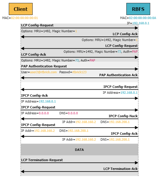
The IP Control Protocol (IPCP) is used to negotiate the configuration of IP addresses and related parameters (such as DNS server, etc.) between the client and the BNG. The peer initiating the connection sends an IPCP Configuration Request message to the remote side including the desired IP address and any other IP-related configuration options. The receiver responds with an IPCP Configuration Acknowledgment message, indicating that it has received the request and accepts it. If the receiver does not want to accept the parameters, it can send an IPCP Configuration Not Acknowledge (NAck) and reject the parameters. At the same time, it can suggest alternative parameters.
| There is a separate control protocol for each supported network layer protocol, i.e., IPCP is only used for negotiating IPv4 parameters. For IPv6, the IPv6 Control Protocol (IPv6CP or IP6CP) is used. |
Once IPCP negotiation is successful, the PPP link is considered established and data traffic is forwarded between user’s device and the BNG.
The PPP session can be terminated by either side using LCP Termination Request. Reasons for PPP session termination can be user initiated, session timeouts, or link layer failures.
PPPoE Configuration
Building Blocks
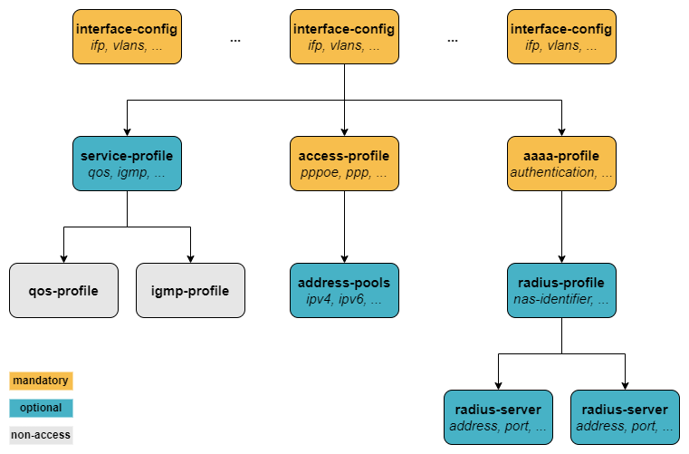
In order to configure PPPoE subscriber services, there are three mandatory configuration blocks:
-
access-profile configuration
-
aaa-profile configuration
-
access interface configuration
Basic Access Profile Configuration
The access profile defines the access protocol being used by the customer, i.e., in our scenario PPPoE. In addition, address families must be enabled explicitly and the mechanism of the address assignment must be defined, being either static or via a pre-defined address pool.
An IP address pool is a set of continuous IP addresses that is locally defined on the BNG and used for address assignment to the subscriber. An address pool is defined using the set access pool <pool_name> ipv4-address|ipv6-prefix syntax.
Configure an IPv4 address pool named PPPOE_POOL_IPV4 with addresses within the range 192.168.164.0/22.
In order to make these IPv4 addresses reachable, they need to be distributed via BGP to other peers. Create a static route 192.168.160.0/20 with next-hop null0 and redistribute this static route into BGP. Note, that the static route covers a large prefix allowing to configure additional pools later.
Click to reveal the answer
cfg> set access pool PPPOE_POOL_IPV4 ipv4-address low 192.168.164.0
cfg> set access pool PPPOE_POOL_IPV4 ipv4-address high 192.168.167.255
cfg> set instance default static route ipv4 192.168.160.0/20 unicast DISCARD
cfg> set instance default static nexthop-profile DISCARD exit-interface null0
cfg> set instance default protocol bgp address-family ipv4 unicast redistribute static
cfg> commit| Address pools can be removed and changed without impact to existing subscribers. This means that they remain the address from a pool after pool is deleted. |
Once you have configured an IP address pool, you can monitor it via the show subscriber pool command:
cfg> show subscriber pool summary
Pool Name                        AFI  Usage           Range
PPPOE_POOL_IPV4                  IPv4 0/1024          192.168.164.0 - 192.168.167.255
Now that we have an IPv4 address pool defined, let’s configure the access-profile via the set access access-profile <profile_name> CLI syntax. Within the access-profile, there are the following steps that need to be configured:
-
The access
protocolneeds to be defined.-
In case of PPPoE,
pppoeneeds to be enabled to support PPPoE session establishment. -
As PPP runs on top of PPPoE,
ppp ipcporppp ip6cpor both need to be enabled and thesource-iflparameter needs to be set. -
Optionally, the
authentication-protocolneeds to be set in theppp lcpprotocol section.
-
-
The corresponding
address-familyneeds to be enabled and the IP address pool needs to be associated with the access-profile. Optionally, DNS servers can be configured.
Configure an access profile named PPPOE_ACCESS. The profile should support IPv4 only and authentication should be set to PAP_CHAP. Also define interface lo-0/0/0/0 as source-ifl.
Associate the IPv4 address pool PPPOE_POOL_IPV4 defined in the last exercise with this profile. Also add DNS servers 192.168.200.1 and 192.168.200.2 to the access-profile definition.
Click to reveal the answer
cfg> set access access-profile PPPOE_ACCESS instance default
cfg> set access access-profile PPPOE_ACCESS protocol pppoe enable true
cfg> set access access-profile PPPOE_ACCESS protocol ppp lcp authentication-protocol PAP_CHAP
cfg> set access access-profile PPPOE_ACCESS protocol ppp ipcp enable true
cfg> set access access-profile PPPOE_ACCESS protocol ppp ipcp source-ifl lo-0/0/0/0
cfg> set access access-profile PPPOE_ACCESS address-family ipv4 enable true
cfg> set access access-profile PPPOE_ACCESS address-family ipv4 pool-name PPPOE_POOL_IPV4
cfg> set access access-profile PPPOE_ACCESS address-family ipv4 primary-dns 192.168.200.1
cfg> set access access-profile PPPOE_ACCESS address-family ipv4 secondary-dns 192.168.200.2
cfg> commit
Note, that the default routing-instance is default, so this command can be skipped.
AAA Profile Configuration
Subscriber management requires the mandatory configuration of an Authentication, Authorization, and Accounting (AAA) profile. For authentication, local authentication based on locally defined user profiles and RADIUS authentication are supported as well as disabling authentication by accepting all credentials.
The AAA profile is configured using the set access aaa-profile <profile_name> syntax hierarchy. The simplest aaa-profile disables the authentication using the keyword NONE (which accepts all sessions) and skipping any accounting definition.
Configure an AAA profile named PPPOE_AUTH. The AAA profile should not support any accounting and authentication should be set to NONE.
Click to reveal the answer
cfg> set access aaa-profile PPPOE_AUTH authentication order NONE
cfg> commit
Access Interface Configuration
A customer is connected to a physical interface of the BNG. Due to aggregation of multiple customers within the access network, a customer line is typically represented by one VLAN (single-tagged) or two VLANs (double-tagged) on a physical interface with a limitation to one session, which is also called the 1:1 VLAN mode.
| It is also possible that multiple customers share the same VLAN which is called N:1 VLAN mode. This mode typically requires a per VLAN limitation set to the maximum number of sessions per VLAN with an additional limitation of one session per MAC. |
In contrast to routed interfaces, access interfaces are defined using the set access interface command hierarchy. There are four major configuration tasks that need to be done:
-
Configure the type (
untagged,single-tagged, ordouble-tagged) along with the physical interface name (IFP) and the corresponding VLAN range in case ofsingle-tagged, ordouble-tagged. -
Configure the mandatory access type to be
PPPoE -
Associate the access profile with the access interface configuration
-
Associate the AAA profile with the access interface configuration
-
Optionally, additional attributes like service profile or session limits can be configured.
Configure hostif-0/0/4 to support PPPoE subscribers. Subscriber will use double-tagged VLANs (outer VLAN range: 128-159, inner VLAN range: 101-200). Associate the access-profile and aaa-profile configured in previous exercises to the access interface configuration.
Click to reveal the answer
cfg> set access interface double-tagged hostif-0/0/4 128 159 101 200 access-type PPPoE
cfg> set access interface double-tagged hostif-0/0/4 128 159 101 200 access-profile-name PPPOE_ACCESS
cfg> set access interface double-tagged hostif-0/0/4 128 159 101 200 aaa-profile-name PPPOE_AUTH
cfg> commit
Monitoring PPPoE Subscribers
In order to see some useful CLI output, we need some PPPoE subscribers to establish sessions with our RBFS device. The virtual lab environment comes with a service node (SN) that has BNG Blaster pre-installed - an open-source test tool that allows to emulate PPPoE subscribers. A short introduction to the BNG Blaster can be found in the Supplementary Material in section BNG Blaster. For more details refer to the BNG Blaster Documentation.
Now let’s open another terminal, log into the service node and start the BNG Blaster.
student@tour:~$ rtb-ssh SN
Logging into SN as supervisor ...
<...>
supervisor@SN:~ $ sudo bngblaster -C subscriber_pppoe_v4only.json -c 3
[sudo] password for supervisor:
Jul 19 10:43:40.400732 Resolve network interfaces
Jul 19 10:43:40.400887 All network interfaces resolved
Jul 19 10:43:41.514560 ALL SESSIONS ESTABLISHED
The password for user supervisor is simply supervisor on the virtual training environment.
|
Once the message ALL SESSIONS ESTABLISHED appears on the screen, you can switch to the RBFS CLI and execute some monitoring commands. The BNG Blaster session is terminated using Ctrl+c. The switch -c 3 instructs the BNG Blaster to establish 3 sessions. You can vary the number of session count. You can also execute the BNG Blaster with the option -I which start the interactive mode.
Switching back to the RBFS CLI, we can verify that three PPPoE sessions are active. You can use either the show subscriber and the show pppoe session command to verify the status of the subscriber sessions. While the first one is more generic and also applies to other subscriber types (e.g., ipoe), the second one is applicable to PPPoE subscribers only.
cfg> show subscriber
Subscriber-Id          Interface        VLAN      Type   State
72339069014638712      hostif-0/0/4     128:101   PPPoE  ESTABLISHED
72339069014638713      hostif-0/0/4     128:102   PPPoE  ESTABLISHED
72339069014638714      hostif-0/0/4     128:103   PPPoE  ESTABLISHED
cfg> show pppoe session
Subscriber-Id          Interface        VLAN      MAC               State
72339069014638712      hostif-0/0/4     128:101   02:00:00:00:00:01 ESTABLISHED
72339069014638713      hostif-0/0/4     128:102   02:00:00:00:00:02 ESTABLISHED
72339069014638714      hostif-0/0/4     128:103   02:00:00:00:00:03 ESTABLISHED
The state ESTABLISHED means that the session is fully operational. When a large number of subscribers are online, the list whole subscriber list might not be useful to start with. You can get an overview of active subscribers on a per box, per interfaces and per protocol basis using the command show subscriber count (or show pppoe session count):
cfg> show subscriber count
                       Total        Setup        Established  Terminating  Standby
Summary                3            0            3            0            0
  PPPoE                3            0            3            0            0
  L2TP                 0            0            0            0            0
  IPoE                 0            0            0            0            0
  L2BSA                0            0            0            0            0
  Test                 0            0            0            0            0
hostif-0/0/4           3            0            3            0            0
  PPPoE                3            0            3            0            0
  L2TP                 0            0            0            0            0
  IPoE                 0            0            0            0            0
  L2BSA                0            0            0            0            0
  Test                 0            0            0            0            0
cfg> show pppoe session count

Global:
    Total:                  3
    Established:            3

Interface hostif-0/0/4:
    Total:                  3
    Established:            3
If you are interested in a specific subscriber, the show subscriber commands offers some filter options to limit the output. Filters can be applied for subscriber mac addresses (mac), the subscriber state (state), or vlans (inner-vlan and/or outer-vlan), among others.
cfg> show pppoe session filter outer-vlan 128 inner-vlan 102
Subscriber-Id          Interface        VLAN      MAC               State
72339069014638713      hostif-0/0/4     128:102   02:00:00:00:00:02 ESTABLISHED
Once you have learned the subscriber identifier, you can get more specific information about the subscriber session:
cfg> show pppoe session 72339069014638713 detail
Subscriber-Id: 72339069014638713                 (1)
    State: ESTABLISHED
    Uptime: Tue Jul 25 09:02:05 GMT +0000 2023 (0:04:12.943096)
    Interface: hostif-0/0/4                      (2)
    Outer VLAN: 128                              (2)
    Inner VLAN: 102                              (2)
    Client MAC: 02:00:00:00:00:02
    Server MAC: 7a:77:1f:c0:00:04
    Session-Id: 120
    Agent-Remote-Id: GLOBAL.RTBRICK.2
    Agent-Circuit-Id: 0.0.0.0/0.0.0.0 eth 0:2
    Access-Profile: PPPOE_ACCESS
    AAA-Profile: PPPOE_AUTH
    PPP LCP:                                     (3)
        State: OPENED
        Negotiated Protocols: PAP, IPCP
        Negotiated Parameters: MRU, AUTH, MAGIC
        Magic Number: 4068147164 Peer: 2
        MRU: 1492 Peer: 1492
        MTU: 1492 Profile: __default_pppoe__
    PAP Authentication:
        State: COMPLETED
        Username: user2@rtbrick.com              (4)
    PPP IPCP:                                    (5)
        State: OPENED
        Peer IP Address: 192.168.164.9
        Local IP Address: 192.168.0.1
        Primary DNS: 192.168.200.1 Assigned: True
        Secondary DNS: 192.168.200.2 Assigned: True
    Control Traffic Statistics:
        Ingress: 15 packets 701 bytes
Egress: 15 packets 697 bytes| 1 | Each subscriber is uniquely identified by a 64bit number called subscriber-id. |
| 2 | Incoming interface and the corresponding VLANs of the subscribers are displayed. |
| 3 | LCP session parameters including negotiated protocols |
| 4 | PPP username |
| 5 | IP-related information including leased IPv4 address and DNS servers are listed. |
Similar information can be retrieved using the show subscriber <subscriber-id> detail command.
|
Finally, you can monitor the usage of the IP address pools defined on the node:
cfg> show subscriber pool summary
Pool Name                        AFI  Usage           Range
PPPOE_POOL_IPV4                  IPv4 3/1024          192.168.164.0 - 192.168.167.255
cfg> show subscriber pool ipv4 PPPOE_POOL_IPV4 allocation

Subscriber-Id          Timestamp                            Address/Prefix
72339069014638712      Tue Jul 25 09:02:05 GMT +0000 2023   192.168.164.1
72339069014638713      Tue Jul 25 09:02:05 GMT +0000 2023   192.168.164.2
72339069014638714      Tue Jul 25 09:02:05 GMT +0000 2023   192.168.164.3
When users are experiencing connectivity issues, it is often useful to see the history of their disconnections. RBFS provides the show subscriber history command which provides the reason why subscribers are terminated for the last 24 hours. In case of hundreds or thousands of users, the command supports a filter knob to limit the amount of output:
cfg> show subscriber history filter username-regex user2
Subscriber-Id          Type   Timestamp                            Username                                 Terminate Code
72339069014638595      PPPoE  Thu Jul 27 06:21:29 GMT +0000 2023   user2@rtbrick.com                        PPPoE LCP Terminate Request Received
72339069014638600      PPPoE  Thu Jul 27 06:35:18 GMT +0000 2023   user2@rtbrick.com                        PPPoE LCP Terminate Request Received
RADIUS Authentication and Accounting
We already know that configuring subscriber management services requires the configuration of an aaa-profile. For beginning, we have set the authentication method to NONE in order to bypass the authentication. Next, we will add RADIUS authentication and accounting to our configuration.
RADIUS Overview
Remote Authentication Dial-In User Service (RADIUS) is a networking protocol used for centralized authentication, authorization, and accounting (AAA) for users who connect and access network services. In the context of broadband internet access, RADIUS plays a critical role in authenticating users and granting them access to the ISP’s network.
When a subscriber connects to the BNG, the BNG sends an authentication request to the RADIUS server. Note, that in RADIUS terminology the BNG is called network access server (NAS). The RADIUS server is responsible for validating the user’s credentials, such as username and password, against a centralized user database. If the credentials are correct, the RADIUS server responds to the NAS with an authentication success message, allowing the user’s device to access the network.
RADIUS also facilitates accounting and logging of user activities, including the duration of the session, data usage, and other relevant information. This information can be used for billing purposes and network management.
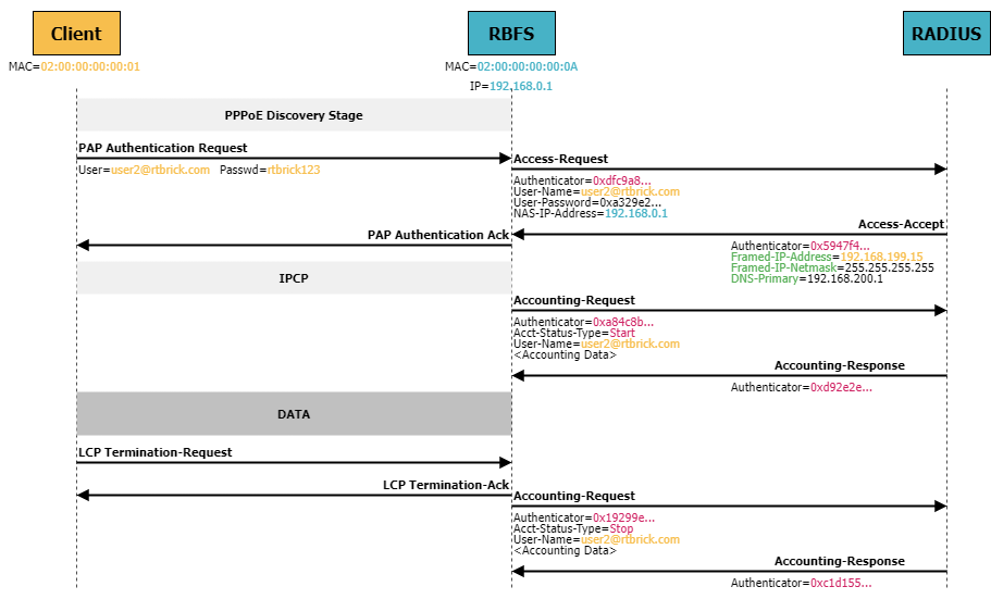
RADIUS messages encode specific information about a user or session using key-value pairs called RADIUS attributes. Each attribute has a unique identifier (attribute number) and contains a value associated with that identifier. These attributes are used to communicate between the RADIUS client (e.g., the BNG) and the RADIUS server, which is responsible for handling the authentication of users. Some common RADIUS attributes include User-Name and User-Password. There are also vendor-specific attributes (VSAs) defined by vendors to carry proprietary information or additional features.
Configuring RADIUS Authentication
The first step is to define one or more RADIUS servers using the set access radius-server command hierarchy. The radius-server configuration includes the IP address of the RADIUS server, the source address and the routing-instance used by RBFS to send the RADIUS messages, as well as the key to authenticate the RADIUS messages (either in plain text or encrypted). Furthermore, authentication and/or accounting need to be enabled and optionally the ports need to be defined if the differ from the default ports (1812 for authentication and 1813 for accounting).
Configure a RADIUS server named SN with IP address of 172.16.101.18. The secret key should be set to SecretKey. Also enable authentication and use non-default port 1645.
Note, that you have no IP connectivity to the RADIUS server which is directly connected to R1. Configure hostif-0/0/0 with VLAN 20 and IP address of 172.16.101.17/28 and use this address as source-address for communication with the RADIUS server.
Click to reveal the answer
cfg> set interface hostif-0/0/0 unit 20 instance default
cfg> set interface hostif-0/0/0 unit 20 vlan 20
cfg> set interface hostif-0/0/0 unit 20 address ipv4 172.16.101.17/28
cfg> set access radius-server SN address 172.16.101.18
cfg> set access radius-server SN source-address 172.16.101.17
cfg> set access radius-server SN secret-plain-text SecretKey
cfg> set access radius-server SN routing-instance default
cfg> set access radius-server SN authentication enable true
cfg> set access radius-server SN authentication port 1645
cfg> commit
You can verify the proper configuration of the RADIUS server using the show radius server command which lists all available RADIUS servers including their authentication and accounting state.
cfg> show radius server
RADIUS Server            Address          Authentication State Accounting State
SN                       172.16.101.18    ACTIVE               DISABLED
Next, we need to create a RADIUS profile via the set access radius-profile <profile_name> syntax hierarchy. The RADIUS profile defines the network access server (NAS), which in our case is the BNG device. It also defines which RADIUS servers are to be used for authentication and accounting. A RADIUS profile can contain multiple RADIUS servers for sake of redundancy or load balancing. If several servers are used, then you can define the algorithm-type to be either DIRECT (same server is used unless it fails) or ROUND-ROBIN.
Configure a RADIUS profile named MYRADIUS which includes the RADIUS server SN defined in the last exercise for authentication. Set the nas-identifier to BNG, the nas-ip-address to your lo-0/0/0/0 address and the nas-port-type to Ethernet.
Click to reveal the answer
cfg> set access radius-profile MYRADIUS nas-identifier BNG
cfg> set access radius-profile MYRADIUS nas-ip-address 192.168.0.1
cfg> set access radius-profile MYRADIUS nas-port-type Ethernet
cfg> set access radius-profile MYRADIUS authentication radius-server-profile-name SN
cfg> commit
Finally, we need to modify the existing AAA profile which is currently set to skip authentication.
In a previous exercise, the authentication was set to NONE for AAA profile PPPOE_AUTH. Update the configuration to use RADIUS for authentication and associate the MYRADIUS profile with the AAA profile.
Click to reveal the answer
cfg> set access aaa-profile PPPOE_AUTH aaa-radius-profile MYRADIUS
cfg> set access aaa-profile PPPOE_AUTH authentication order RADIUS
cfg> commit
Now, let’s check that RADIUS authentication is working. Therefore, we log into the service node SN once again and restart BNG Blaster with session count of three. As a result, we can verify that all PPPoE sessions are established:
cfg> show pppoe session
Subscriber-Id          Interface        VLAN      MAC               State
72339069014638841      hostif-0/0/4     128:101   02:00:00:00:00:01 ESTABLISHED
72339069014638842      hostif-0/0/4     128:102   02:00:00:00:00:02 ESTABLISHED
72339069014638843      hostif-0/0/4     128:103   02:00:00:00:00:03 ESTABLISHED
Looking at the IP address pool utilization, we notice that only two IPv4 addresses are used from the pool, although we have three active PPPoE sessions:
cfg> show subscriber pool summary
Pool Name                        AFI  Usage           Range
PPPOE_POOL_IPV4                  IPv4 2/1024          192.168.164.0 - 192.168.167.255
PPPOE_POOL_IPV6                  IPv6 2/1024          fc00:c0a8:ff01:400::/64 - fc00:c0a8:ff01:7ff::/64
PPPOE_POOL_V6PD                  IPv6 2/1024          fc00:c0a8:ff14::/56 - fc00:c0a8:ff17:ff00::/56
cfg> show subscriber pool ipv4 PPPOE_POOL_IPV4 allocation
Subscriber-Id          Timestamp                            Address/Prefix
72339069014638842      Tue Jul 25 11:19:14 GMT +0000 2023   192.168.164.20
72339069014638843      Tue Jul 25 11:19:14 GMT +0000 2023   192.168.164.21
After we have identified which PPPoE subscriber has no IP address allocation from the local IP address pool, we can analyze the subscriber details a little more:
cfg> show pppoe session 72339069014638844 detail
Subscriber-Id: 72339069014638844
    State: ESTABLISHED
    Uptime: Tue Jul 25 11:22:09 GMT +0000 2023 (0:00:17.339013)
    Interface: hostif-0/0/4
    Outer VLAN: 128
    Inner VLAN: 101
    Client MAC: 02:00:00:00:00:01
    Server MAC: 7a:77:1f:c0:00:04
    Session-Id: 251
    Agent-Remote-Id: GLOBAL.RTBRICK.1
    Agent-Circuit-Id: 0.0.0.0/0.0.0.0 eth 0:1
    Access-Profile: PPPOE_ACCESS
    AAA-Profile: PPPOE_AUTH
    PPP LCP:
        State: OPENED
        Negotiated Protocols: PAP, IPCP
        Negotiated Parameters: MRU, AUTH, MAGIC
        Magic Number: 2130026357 Peer: 1
        MRU: 1492 Peer: 1492
        MTU: 1492 Profile: __default_pppoe__
    PAP Authentication:
        State: COMPLETED
        Username: user1@rtbrick.com
    PPP IPCP:
        State: OPENED
        Peer IP Address: 192.168.170.5                (1)
        Local IP Address: 192.168.0.1
        Primary DNS: 192.168.200.3 Assigned: True     (2)
        Secondary DNS: 192.168.200.4 Assigned: True   (2)
    Control Traffic Statistics:
        Ingress: 7 packets 365 bytes
Egress: 7 packets 361 bytes| 1 | IP address assigned by RADIUS server |
| 2 | DNS server assigned by RADIUS server |
It turns out, that this subscriber got an IP address from the RADIUS server directly and did not consume an IP address from the local pool. In addition, the DNS servers are different than the ones defined in our access profile.
| RADIUS attributes can overwrite generic parameters that are defined in profiles. When a user is successfully authenticated by a RADIUS server, the RADIUS server can send specific attributes back to the BNG based on the user’s identity or other criteria. Thus, RADIUS attributes can be used to define specific IP address assignments, access control lists, bandwidth limits, or any other parameter relevant to the user’s session. These attributes will take precedence over generic settings. |
Using RADIUS to manage session parameters of subscribers is a very common deployment model in broadband access as it allows to maintain user information in a central database, reduces the amount of local configuration and simplifies user migration from one device to another.
Configuring RADIUS Accounting
RADIUS accounting is used to collect data for statistical, monitoring and subscriber billing purposes. Once a user is granted access by the RADIUS server, the BNG sends an Accounting Start message to the RADIUS server containing username and the unique session identifier. When a particular subscriber session is terminated, the BNG sends a Accounting Stop message with comprehensive session information such as total time, data and packets transferred, etc., to the RADIUS server. In addition, the BNG can also send Interim Updates at regular intervals to reduce loss of information in the event of loss of an Accounting Stop message and also to provide a more detailed picture for long-live sessions.
Configure the following steps to enable RADIUS accounting:
-
Enable
accountingwith port 1646 in your RADIUS server configuration -
Add the RADIUS server to your radius-profile as accounting server
-
Add
accountingto your aaa-profile. Set theinterim-intervalto 30.
Click to reveal the answer
cfg> set access radius-server SN accounting enable true
cfg> set access radius-server SN accounting port 1646
cfg> set access radius-profile MYRADIUS accounting radius-server-profile-name SN
cfg> set access aaa-profile PPPOE_AUTH accounting order RADIUS
cfg> set access aaa-profile PPPOE_AUTH accounting interim-interval 30
cfg> commit
cfg> show radius server
RADIUS Server Address Authentication State Accounting State
SN 172.16.101.18 UP ACTIVESubscriber accounting is based on multiple sources, e.g.,
-
Session counters are calculated using the LIF statistics by default
-
Class counters are filled by queue counters which ensures that only traffic leaving the device is counted here.
-
Policy counters are populated by ingress policers.
| Accounting information in RBFS is based on hardware resource of the device. Therefore, in virtual nodes all counters are zero. |
Now let’s start the BNG Blaster once again. We can now verify that accounting is enabled:
cfg>
show subscriber 72339069014638832 accounting
Subscriber-Id: 72339069014638832
    IFL: ppp-0/0/4/72339069014638832
    Start Timestamp: Tue Jul 25 10:41:48 GMT +0000 2023
    Idle Timestamp: never
    Session-Timeout: 0 seconds
    Idle-Timeout: 0 seconds
    Session Statistics:
        Ingress: 0 packets 0 bytes
        Egress: 0 packets 0 bytes
    LIF Statistics:
        Ingress: 0 packets 0 bytes
        Egress: 0 packets 0 bytes
    Egress Class (Queue) Statistics:
        class-0: 0 packets 0 bytes dropped: 0 packets 0 bytes
        class-1: 0 packets 0 bytes dropped: 0 packets 0 bytes
        class-2: 0 packets 0 bytes dropped: 0 packets 0 bytes
        class-3: 0 packets 0 bytes dropped: 0 packets 0 bytes
        class-4: 0 packets 0 bytes dropped: 0 packets 0 bytes
        class-5: 0 packets 0 bytes dropped: 0 packets 0 bytes
        class-6: 0 packets 0 bytes dropped: 0 packets 0 bytes
        class-7: 0 packets 0 bytes dropped: 0 packets 0 bytes
    Ingress Policer Statistics:
        Level 1: 0 packets 0 bytes dropped: 0 packets 0 bytes
        Level 2: 0 packets 0 bytes dropped: 0 packets 0 bytes
        Level 3: 0 packets 0 bytes dropped: 0 packets 0 bytes
        Level 4: 0 packets 0 bytes dropped: 0 packets 0 bytes
More important, these information are written to the RADIUS server. Switching to the service node (SN), you can find the accounting messages in file /var/log/radius/detail.log
IPv6 Support
PPPoE subscribers can be either single-stack IPv4, single-stack IPv6 or dual-stack. So far, we have configured our subscriber to be single-stack IPv4. The same configuration steps are necessary to enable IPv6 support. The main difference between IPv4 and IPv6 is that PPPoE subscribers usually get two IPv6 prefixes, one for the link between residential gateway and BNG and another one to use within the customer’s LAN. The later one is called a delegated prefix and removes the need for NAT.
Configure two IPv6 address pools, IPOE_POOL_IPV6 (fc00:c0a8:ff01:0400::/64 - fc00:c0a8:ff01:07ff::/64) and IPOE_POOL_V6PD (fc00:c0a8:ff14:0000::/56 - fc00:c0a8:ff17:ff00::/56). Also add two static routes fc00:c0a8:ff01::/52 and fc00:c0a8:ff10::/44 to the configuration and redistribute them into BGP.
Note, that the static routes cover more prefixes than the configured IPv6 address pools to allow extension in the future.
Click to reveal the answer
cfg> set access pool PPPOE_POOL_IPV6 ipv6-prefix low fc00:c0a8:ff01:0400::/64
cfg> set access pool PPPOE_POOL_IPV6 ipv6-prefix high fc00:c0a8:ff01:07ff::/64
cfg> set access pool PPPOE_POOL_V6PD ipv6-prefix low fc00:c0a8:ff14:0000::/56
cfg> set access pool PPPOE_POOL_V6PD ipv6-prefix high fc00:c0a8:ff17:ff00::/56
cfg> set instance default static route ipv6 fc00:c0a8:ff01::/52 unicast PPPOE_POOL
cfg> set instance default static route ipv6 fc00:c0a8:ff10::/44 unicast PPPOE_POOL
cfg> set instance default protocol bgp address-family ipv6 unicast redistribute static
cfg> commitUpdate the existing access profile PPPOE_ACCESS by enabling ip6cp protocol and address-family ipv6. Also add the IPv6 address pool and delegated prefix pool as well as two DNS servers (fc00:c0a8:ffff::1 and fc00:c0a8:ffff::2) to the existing access profile.
Click to reveal the answer
cfg> set access access-profile PPPOE_ACCESS protocol ppp ip6cp enable true
cfg> set access access-profile PPPOE_ACCESS address-family ipv6 enable true
cfg> set access access-profile PPPOE_ACCESS address-family ipv6 pool-name PPPOE_POOL_IPV6
cfg> set access access-profile PPPOE_ACCESS address-family ipv6 prefix-delegation-pool-name PPPOE_POOL_V6PD
cfg> set access access-profile PPPOE_ACCESS address-family ipv6 primary-dns fc00:c0a8:ffff::1
cfg> set access access-profile PPPOE_ACCESS address-family ipv6 secondary-dns fc00:c0a8:ffff::2
cfg> commit
Now let’s open another terminal, log into the service node and start the BNG Blaster again. We now need another BNG Blaster configuration file (subscriber_pppoe_dualstack.json) to include IPv6:
student@tour:~$ rtb-ssh SN
Logging into SN as supervisor ...
<...>
supervisor@SN:~ $ sudo bngblaster -C subscriber_pppoe_dualstack.json -c 3
[sudo] password for supervisor:
Jul 19 10:43:40.400732 Resolve network interfaces
Jul 19 10:43:40.400887 All network interfaces resolved
Jul 19 10:43:41.514560 ALL SESSIONS ESTABLISHED
Verifying that PPPoE subscribers sessions are established and utilization of IP address pool can be monitored exactly the same way as with IPv4-only subscribers:
cfg> show pppoe session
Subscriber-Id          Interface        VLAN      MAC               State
72339069014638838      hostif-0/0/4     128:101   02:00:00:00:00:01 ESTABLISHED
72339069014638839      hostif-0/0/4     128:102   02:00:00:00:00:02 ESTABLISHED
72339069014638840      hostif-0/0/4     128:103   02:00:00:00:00:03 ESTABLISHED
cfg> show subscriber pool summary
Pool Name                        AFI  Usage           Range
PPPOE_POOL_IPV4                  IPv4 2/1024          192.168.164.0 - 192.168.167.255
PPPOE_POOL_IPV6                  IPv6 2/1024          fc00:c0a8:ff01:400::/64 - fc00:c0a8:ff01:7ff::/64
PPPOE_POOL_V6PD                  IPv6 2/1024          fc00:c0a8:ff14::/56 - fc00:c0a8:ff17:ff00::/56
Diving into more details of a specific subscriber you notice that now additional information about the IPv6 are available:
cfg> show pppoe session 72339069014638839 detail
Subscriber-Id: 72339069014638839
    State: ESTABLISHED
    Uptime: Tue Jul 25 11:04:37 GMT +0000 2023 (0:03:46.470351)
    Interface: hostif-0/0/4
    Outer VLAN: 128
    Inner VLAN: 102
    Client MAC: 02:00:00:00:00:02
    Server MAC: 7a:77:1f:c0:00:04
    Session-Id: 246
    Agent-Remote-Id: GLOBAL.RTBRICK.2
    Agent-Circuit-Id: 0.0.0.0/0.0.0.0 eth 0:2
    Access-Profile: PPPOE_ACCESS
    AAA-Profile: PPPOE_AUTH
    PPP LCP:
        State: OPENED
        Negotiated Protocols: PAP, IPCP, IP6CP   (1)
        Negotiated Parameters: MRU, AUTH, MAGIC
        Magic Number: 729972578 Peer: 2
        MRU: 1492 Peer: 1492
        MTU: 1492 Profile: __default_pppoe__
    PAP Authentication:
        State: COMPLETED
        Username: user2@rtbrick.com
    PPP IPCP:
        State: OPENED
        Peer IP Address: 192.168.164.18
        Local IP Address: 192.168.0.1
        Primary DNS: 192.168.200.1 Assigned: True
        Secondary DNS: 192.168.200.2 Assigned: True
    PPP IP6CP:                                   (2)
        State: OPENED
        Interface Identifier: 42f1:9885:280d:2965
        Peer Interface Identifier: 0200:00ff:fe00:0002
    IPv6:                                        (3)
        RA Interval: disabled
        RA Prefix: fc00:c0a8:ff01:402::/64
        Delegated Prefix (DHCPv6): fc00:c0a8:ff14:200::/56 Assigned: False  (4)
        Primary DNS: fc00:c0a8:ffff::1
        Secondary DNS: fc00:c0a8:ffff::2
    Control Traffic Statistics:
        Ingress: 61 packets 4479 bytes
Egress: 15 packets 697 bytes| 1 | With IP6CP enabled, it is enlisted in the negotiated protocols. |
| 2 | The PPP IP6CP state is now opened. |
| 3 | The IPv6 section displays the assigned prefixes and DNS server entries. |
| 4 | Note, that delegated prefix assignment is false. |
From the above output we can see that although a delegated prefix has been reserved for the subscriber, the assignment is inactive. We can’t verify that no corresponding route was created either:
cfg> show route ipv6 source ppp
Instance: default, AFI: ipv6, SAFI: unicast
Prefix/Label                             Source            Pref    Next Hop                                 Interface
fc00:c0a8:ff01:402::/64                  ppp               8       -                                        ppp-0/0/4/72339069014638839
fc00:c0a8:ff01:403::/64                  ppp               8       -                                        ppp-0/0/4/72339069014638840
fc00:c0a8:ff01:c01::/64                  ppp               8       -                                        ppp-0/0/4/72339069014638838
As a result, there is no IPv6 traffic forwarded. The reason is that the delegated prefix is assigned via DHCPv6. However, no DHCPv6 is activated in our profile. We can fix this issue by enabling DHCPv6 and IPv6 router advertisements within the access profile.
Update the existing access profile PPPOE_ACCESS by enabling dhcpv6 protocol and ra protocol.
Click to reveal the answer
cfg> set access access-profile PPPOE_ACCESS protocol ra enable true
cfg> set access access-profile PPPOE_ACCESS protocol dhcpv6 enable true
cfg> commit
cfg> show route ipv6 source ppp
Instance: default, AFI: ipv6, SAFI: unicast
Prefix/Label                             Source            Pref    Next Hop                                 Interface
fc00:c0a8:ff01:40a::/64                  ppp               8       -                                        ppp-0/0/4/72339069014638842
fc00:c0a8:ff01:40b::/64                  ppp               8       -                                        ppp-0/0/4/72339069014638843
fc00:c0a8:ff01:c01::/64                  ppp               8       -                                        ppp-0/0/4/72339069014638841
fc00:c0a8:ff14:a00::/56                  ppp               8       -                                        ppp-0/0/4/72339069014638842
fc00:c0a8:ff14:b00::/56                  ppp               8       -                                        ppp-0/0/4/72339069014638843
fc00:c0a8:ff1c:100::/56                  ppp               8       -                                        ppp-0/0/4/72339069014638841
Summary
This module outlined the building blocks of PPPoE subscriber management. You should be familiar with concepts of PPPoE session setup as well as RADIUS authentication and accounting. In addition, you should be able to setup access profiles and aaa profiles.
If you have completed the exercise, you can check the results by executing
student@tour:~/trainings_resources/robot$ robot pppoe/pppoe_verify.robot