MPLS/BGP Layer-3 VPN (L3VPN)
Module Introduction
Before you start the hands-on part of this module, you should load the appropriate configuration and verify that the testbed is up and running by executing the corresponding robot file:
student@tour:~/trainings_resources/robot$ robot mpls_l3vpn/mpls_l3vpn_setup.robot|
We use IS-IS as IGP for the examples and exercises in this module. The choice of IGP is not important for understanding and configuration of Layer-3 VPNs. However, if you prefer to run OSPF instead, you can alternatively load the setup using the |
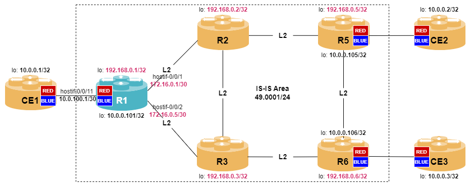
In order to get a better understanding, the lab setup is shown in the picture below.
VPN Overview
A Virtual Private Network (VPN) is a network that allows secure connectivity between multiple locations across a shared infrastructure. Note, that secure does not necessarily mean encrypted. The parties being connected are called customers (or tenants in data centers).
Prior to BGP/MPLS-based VPNs, service providers implemented VPN services by an overlay of point-to-point connections using tunneling technologies like ATM, GRE or IPsec with the benefit of customers and service provider being well-isolated. However, the drawback of this approach is that a full mesh of tunnels is needed and that there is a significant encapsulation overhead.
BGP/MPLS-based Layer-3 VPNs (L3VPNs) are peer-to-peer VPNs, i.e., the service provider actively takes part in the customer routing allowing optimal routing between customer locations. In addition, there is no need to pre-provision a full-mesh of connections which simplifies the maintenance of the VPN and the addition of new locations.
Building Blocks
An MPLS VPN has the following building blocks:
-
Customer Edge (CE) router is a non-MPLS router that resides on the customer site and interconnects with the PE router using a standard routing protocol, the most popular choice being BGP or static routing.
-
Customer (C) router is an internal router at the customer site.
-
Provider Edge (PE) router is an LER that interconnects with CE routers and maintains VPN routes for VPNs that are implemented on the PE router. The PE router exchanges routing information with the CE router.
-
Provider (P) router is an LSR that resides in the core of the network and does not maintain any VPN-related state, i.e., it does not take part in signaling of customer related routing information. P routers transparently forward VPN traffic along pre-established LSPs.
-
VPN site is a set of customer devices (CE routers and C routers) that is able to connect without traversing the service provider backbone. A site can be as simple as a single geographic location with a link to a PE router. A site can also be a network spanning multiple geographic locations. A VPN site is attached top at least on PE router, but can also be multihomed to multiple PE routers.
-
VPN Routing and Forwarding (VRF) table is a site-specific routing table maintained by a PE router in order to separate different VPN customers from each other. The VRF table contains routes learned from the attached CE routers as well as routes learned from remote PE routers.
| There is no one-to-one correspondence between VPN and VRF. A VPN site always belongs to a single VRF. However, a VPN site may be a member of multiple VPNs. |
Consider two CE routers CE1 and CE2, where CE1 is member of VPNBLUE and CE2 is member of both, VPNBLUE and VPNGREEN. Both CE routers are connected to the same PE router. Then CE1 and CE2 are attached to two different VRFs because the content of the routing tables associated with CE routers CE1 and CE2 are different.
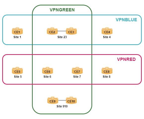
A practical application is a central site VPN which hosts shared services for multiple VPNs, e.g., DNS or NTP servers.
Control Plane
The basic idea for implementing L3VPN is to use a stack of two MPLS labels. The outer label represents the LSP, i.e., the transport path between ingress PE router and egress PE router. The LSP can be signaled and setup using LDP or IS-IS SR, etc.
The inner label is a VPN service label that represents the VRF context on the PE router. This label is exchanged between the PE routers via Multiprotocol Extensions of BGP (MP-BGP).
To solve the problem of separating IP address space between different customers and to allow label distribution for the service, a new BGP sub-address family called labeled VPN address (SAFI 128) is introduced, i.e., AFI/SAFI 1/128 is used for IPv4 VPNs and 2/128 for IPv6 VPNs.
| Do not mix 6PE using AFI/SAFI=2/4 with IPv6 VPN (also called 6VPE) using AFI/SAFI=2/128. The former one being an IPv6 Internet service across MPLS core network, while the later one being a IPv6-enabled VPN service. |
A VPN IPv4 prefix is a 96-bit information that is composed of a 32-bit IPv4 prefix and a 64-bit route distinguisher (RD). As the name implies the route distinguisher is an identifier that helps to keep overlapping address space isolated by converting a IP prefix to a globally unique VPN identifier. In a similar way, a 128-bit IPv6 prefix is converted to a 224-bit VPNv6 prefix by adding the route distinguisher. There are three different ways how to encode a RD:
-
Type 0: 2-byte ASN and 4-byte assigned number, e.g., 64500:100
-
Type 1: 4-byte IPv4 address and 2-byte assigned number, e.g., 10.0.0.1:100
-
Type 2: 4-byte ASN and 2-byte assigned number, e.g., 4200000000:100
| It is best practice to have a different route distinguisher per VRF. |
When a PE router learns a prefix from the CE router, it stores the route in the VRF table as native IPv4 or IPv6 prefix. In addition, the route is converted to a VPNv4 or VPNv6 route by adding the route distinguisher.
As we have previously seen, a VRF can be a member of multiple VPNs. In addition, not all PE routers have all VRFs configured. Therefore, we need a mechanism to control route distribution. The route target (RT) is a BGP extended community attribute that performs both of these tasks. When a VPNv4 or VPNv6 route is advertised towards other PE routers, one or more route target communities are attached (exported) to the NLRI. On the other hand, a PE router only accepts (imports) a NLRI it receives if it carries certain route targets.
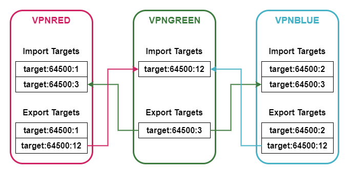
The diagram shows the import and export of route targets for a three VPNs. While VPNRED and VPNBLUE are strictly separated from each other (i.e., there is no import or export of routes between them), the VPNGREEN is a central site VPN offering shared services. This is achieved by using different route targets for import and export.
| Also in some text books and examples the value of route distinguisher and route target are identical, it’s important to understand that both of these identifiers are completely different. The route distinguisher is part of the prefix itself (by converting IPv4 to VPNv4, respectively IPv6 to VPNv6), while the route target is a BGP extended community attribute attached to the NLRI. |
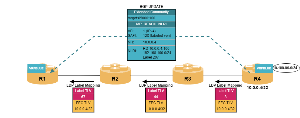
Putting all the components together, PE routers exchange VPN-related routing information by sending BGP update messages containing MP_REACH_NLRI path attributes with appropriate address families. Route filtering is done via the attached route target communities.
Data Plane
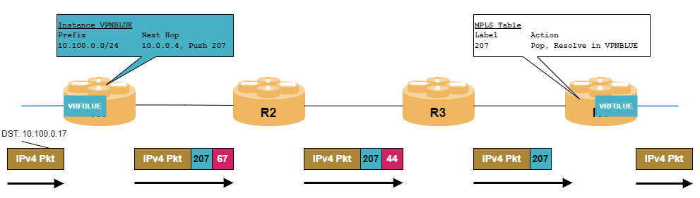
A PE router receives an IPv4 or IPv6 packet on an interface that is associated with a VRF instance. It performs a route lookup in this specific routing table which is populated with route updates exchanged via MP-BGP. As a result, the PE router retrieves two information: a VPN service label that is pushed to the packet and a next hop address. The resolution of the next hop address via the IPv4 labeled-unicast routing table causes a push of a transport label. The packet with two labels is then send to the next hop. In general, there are multiple P routers along the LSP from ingress PE router to egress PE router which only perform label swapping of the outer transport label and eventually perform penultimate hop popping. The egress PE router receives a single labeled packet from the core network that contains the VPN service label. The lookup of this label in its MPLS routing table results in the label being removed and the packet resolved in the corresponding VRF table.
Configuring VRF Instance
|
The MPLS data plane configuration has already been done for you as part of the initial lab setup.
|
The first step is to create a separate VPN routing instance for each customer. The configuration is done using the set instance <vrfname> syntax. In addition, interfaces between PE router and CE router need to be associated with the appropriate routing instance with the set interface <ifname> unit <unit> instance <vrfname> command.
Configure two VRF routing instance named VPNRED and VPNBLUE. Both VPNs are dual-stack IPv4 and IPv6. Enable the corresponding address families and set route-distinguisher and route targets according the following table:
| Instance | RD | Import RT IPv4 | Export RT IPv4 | Import RT IPv6 | Export RT IPv6 |
|---|---|---|---|---|---|
VPNRED |
192.168.0.1:100 |
100:4 |
100:4 |
100:6 |
100:6 |
VPNBLUE |
192.168.0.1:101 |
101:4 |
101:4 |
101:6 |
101:6 |
Configure the VRF interfaces according to the table below.
To configure an IPv6 link-local address on a logical unit, simply enable IPv6 with out setting any addressset interface <interface_name> unit <unit_number> ipv6-admin-status upThis will allow the processing of IPv6 frames from the CEs, without the need of assigning a routable address to PE-CE links. |
| Instance | Interface | Unit | VLAN | IPv4 Address | IPv6 Address |
|---|---|---|---|---|---|
VPNRED |
hostif-0/0/11 |
100 |
100 |
10.0.100.1/30 |
link-local |
VPNRED |
lo-0/0/0 |
100 |
10.0.0.101/32 |
fc00:abc::101/128 |
|
VPNBLUE |
hostif-0/0/11 |
101 |
101 |
10.0.100.1/30 |
link-local |
VPNBLUE |
lo-0/0/0 |
101 |
10.0.0.101/32 |
fc00:abc::101/128 |
Click to reveal the answer
set instance VPNBLUE route-distinguisher 192.168.0.1:101
set instance VPNBLUE address-family ipv4 unicast route-target import target:101:4
set instance VPNBLUE address-family ipv4 unicast route-target export target:101:4
set instance VPNBLUE address-family ipv6 unicast route-target import target:101:6
set instance VPNBLUE address-family ipv6 unicast route-target export target:101:6
set instance VPNRED route-distinguisher 192.168.0.1:100
set instance VPNRED address-family ipv4 unicast route-target import target:100:4
set instance VPNRED address-family ipv4 unicast route-target export target:100:4
set instance VPNRED address-family ipv6 unicast route-target import target:100:6
set instance VPNRED address-family ipv6 unicast route-target export target:100:6
set interface hostif-0/0/11 admin-status up
set interface hostif-0/0/11 unit 100 instance VPNRED
set interface hostif-0/0/11 unit 100 ipv6-admin-status up
set interface hostif-0/0/11 unit 100 vlan 100
set interface hostif-0/0/11 unit 100 address ipv4 10.0.100.1/30
set interface hostif-0/0/11 unit 101 instance VPNBLUE
set interface hostif-0/0/11 unit 101 ipv6-admin-status up
set interface hostif-0/0/11 unit 101 vlan 101
set interface hostif-0/0/11 unit 101 address ipv4 10.0.100.1/30
set interface lo-0/0/0 unit 100 instance VPNRED
set interface lo-0/0/0 unit 100 ipv6-admin-status up
set interface lo-0/0/0 unit 100 address ipv4 10.0.0.101/32
set interface lo-0/0/0 unit 100 address ipv6 fc00:abc::101/128
set interface lo-0/0/0 unit 101 instance VPNBLUE
set interface lo-0/0/0 unit 101 ipv6-admin-status up
set interface lo-0/0/0 unit 101 address ipv4 10.0.0.101/32
set interface lo-0/0/0 unit 101 address ipv6 fc00:abc::101/128

commit
We can check whether the VRF routing instance is active or not using the show instance command:
cfg> show instance VPNRED detail
Instance: VPNRED
  Router ID: 10.0.0.101
  Instance ID: 3
  State: Active
  AFI        SAFI             State
  ipv4       unicast          Active
ipv6 unicast Active| The VRF instance is a IPv4 and/or IPv6 unicast instance. There is no labeled-unicast within the instance. |
Next, we can verify that the interfaces are associated with the correct VRF instance:
cfg> show interface address instance VPNRED
Interface              Instance            IPv4 Address             IPv4 Primary   IPv6 Address
lo-0/0/0/100           VPNRED              10.0.0.101/32            True           fc00:abc::101/128
hostif-0/0/11/100      VPNRED              10.0.100.1/30            True           fe80::7856:c00:64c0:b/64
Finally, let’s have a look at the VRF routing table:
cfg> show route instance VPNRED
Flags: & - Imported
Instance: VPNRED, AFI: ipv4, SAFI: unicast
Flags  Prefix/Label                                Source               Pref  Next Hop                  Outgoing Interface
       10.0.0.101/32                               direct                  0  10.0.0.101                lo-0/0/0/100
       10.0.100.1/32                               direct                  0  10.0.100.1                hostif-0/0/11/100
       10.0.100.0/30                               direct                  0  10.0.100.0                hostif-0/0/11/100
       10.0.100.2/32                               arp-nd                  6  10.0.100.2                hostif-0/0/11/100
Instance: VPNRED, AFI: ipv6, SAFI: unicast
Flags  Prefix/Label                                Source               Pref  Next Hop                  Outgoing Interface
       fc00:abc::101/128                           direct                  0  fc00:abc::101             lo-0/0/0/100
So far, there are only the directly connected interfaces in the routing tables as we have neither configured the PE-PE routing, nor the PE-CE routing.
Configuring BGP for VPNv4/VPNv6
The MP-BGP session between PE routers is configured in the default instance and shared between all VRF instance. Depending on the design of the network, there is the option to either configure a full-mesh of BGP sessions between PE routers or to use a route reflector to improve scalability.
Configure internal BGP session to routers R5 (192.168.0.5) and R6 (192.168.0.6). The AS number is 64500. The supported address families are ipv4 vpn-unicast and ipv6 vpn-unicast.
Click to reveal the answer
set instance default protocol bgp hostname R1
set instance default protocol bgp local-as 64500
set instance default protocol bgp router-id 192.168.0.1
set instance default protocol bgp address-family ipv4 vpn-unicast
set instance default protocol bgp address-family ipv6 vpn-unicast
set instance default protocol bgp peer ipv4 192.168.0.5 192.168.0.1 peer-group INTERN
set instance default protocol bgp peer ipv4 192.168.0.6 192.168.0.1 peer-group INTERN
set instance default protocol bgp peer-group INTERN remote-as 64500
set instance default protocol bgp peer-group INTERN address-family ipv4 vpn-unicast
set instance default protocol bgp peer-group INTERN address-family ipv6 vpn-unicast
commit

cfg> show bgp peer
Instance: default
  Peer                                     Remote AS    State         Up/Down Time               PfxRcvd              PfxSent
  R5                                       64500        Established   0d:00h:00m:09s             10                   0
  R6                                       64500        Established   0d:00h:00m:11s             10                   0
Now that we have BGP sessions up and running, let’s take another look at the VRF instance routing table:
cfg> show route instance VPNRED
Instance: VPNRED, AFI: ipv4, SAFI: unicast
Prefix/Label                             Source            Pref    Next Hop                                 Interface
10.0.0.101/32                            direct            0       10.0.0.101                               lo-0/0/0/100
10.0.100.1/32                            direct            0       10.0.100.1                               hostif-0/0/11/100
10.0.100.0/30                            direct            0       10.0.100.0                               hostif-0/0/11/100
10.0.100.2/32                            arp-nd            6       10.0.100.2                               hostif-0/01/100
Instance: VPNRED, AFI: ipv6, SAFI: unicast
Prefix/Label                             Source            Pref    Next Hop                                 Interface
fc00:abc::101/128                        direct            0       fc00:abc::101                            lo-0/0/0/100
Although a couple of prefixes have been learned via BGP, none was installed into the VRF table. The reason is that the communication between the default routing instance and the VRF instance is implemented by BGP and there is no BGP running in the VRF instances.
Configure BGP in instance VPNRED (ASN 64501) and VPNBLUE (ASN 64502) and enable the IPv4 unicast and IPv6 unicast address family. Also set the instance router-id to the IPv4 address of the corresponding loopback interface.
Click to reveal the answer
set instance VPNRED protocol bgp local-as 64501
set instance VPNRED protocol bgp router-id 10.0.0.101
set instance VPNRED protocol bgp address-family ipv4 unicast
set instance VPNRED protocol bgp address-family ipv6 unicast

set instance VPNBLUE protocol bgp local-as 64502
set instance VPNBLUE protocol bgp router-id 10.0.0.101
set instance VPNBLUE protocol bgp address-family ipv4 unicast
set instance VPNBLUE protocol bgp address-family ipv6 unicast

commit

cfg> show route instance VPNRED
Flags: & - Imported
Instance: VPNRED, AFI: ipv4, SAFI: unicast
Flags  Prefix/Label                                Source               Pref  Next Hop                                    Outgoing Interface
       10.0.0.2/32                                 bgp                   200  192.168.0.5                                 hostif-0/0/1/0
       10.0.0.3/32                                 bgp                   200  192.168.0.6                                 hostif-0/0/2/0
       10.0.0.101/32                               direct                  0  10.0.0.101                                  lo-0/0/0/100
       10.0.0.105/32                               bgp                   200  192.168.0.5                                 hostif-0/0/1/0
       10.0.0.106/32                               bgp                   200  192.168.0.6                                 hostif-0/0/2/0
       10.0.100.1/32                               direct                  0  10.0.100.1                                  hostif-0/0/11/100
       10.0.100.0/30                               direct                  0  10.0.100.0                                  hostif-0/0/11/100
       10.0.100.2/32                               arp-nd                  6  10.0.100.2                                  hostif-0/0/11/100
       10.0.100.4/30                               bgp                   200  192.168.0.5                                 hostif-0/0/1/0
       10.0.100.8/30                               bgp                   200  192.168.0.6                                 hostif-0/0/2/0
Instance: VPNRED, AFI: ipv6, SAFI: unicast
Flags  Prefix/Label                                Source               Pref  Next Hop                                    Outgoing Interface
       fc00:abc::2/128                             bgp                   200  192.168.0.5                                 hostif-0/0/1/0
       fc00:abc::3/128                             bgp                   200  192.168.0.6                                 hostif-0/0/2/0
       fc00:abc::101/128                           direct                  0  fc00:abc::101                               lo-0/0/0/100
       fc00:abc::105/128                           bgp                   200  192.168.0.5                                 hostif-0/0/1/0
       fc00:abc::106/128                           bgp                   200  192.168.0.6                                 hostif-0/0/2/0
The attempt to verify the connectivity with a ping fails because we have not advertised any of our own interface addresses.
cfg> ping 10.0.0.105 source-ip 10.0.0.101 instance VPNRED count 3
Statistics: 3 sent, 0 received, 100% packet lossConfigure redistribution of direct interface for both VRF instances VPNRED and VPNBLUE, and for both address families. Verify that connectivity works between PE routers.
Click to reveal the answer
set instance VPNBLUE protocol bgp address-family ipv4 unicast redistribute direct
set instance VPNBLUE protocol bgp address-family ipv6 unicast redistribute direct
set instance VPNRED protocol bgp address-family ipv4 unicast redistribute direct
set instance VPNRED protocol bgp address-family ipv6 unicast redistribute direct
commit

cfg> ping 10.0.0.105 source-ip 10.0.0.101 instance VPNRED count 3
68 bytes from 10.0.0.105: icmp_seq=1 ttl=64 time=4.8185 ms
68 bytes from 10.0.0.105: icmp_seq=2 ttl=64 time=7.5846 ms
68 bytes from 10.0.0.105: icmp_seq=3 ttl=64 time=.8377 ms
Statistics: 3 sent, 3 received, 0% packet loss
Configuring PE-CE Routing
Routing information between PE router and CE router can be exchanged using standard routing protocols that run within the VRF instance, e.g., OSPF, BGP, or static routing. All of these configuration work exactly like in the default instance. Remember, that all routing exchange with the other PE routers happen via BGP which means that the PE-CE routing protocol must be redistributed into the instance VRF BGP protocol - similar to the direct interfaces. The advantage of using BGP of a PE-CE routing protocol is that you do not explicitly need to redistribute it.
Configure internal BGP as PE-CE routing protocol for both VRF instances VPNRED and VPNBLUE and both address families.
The peer address is the directly connected address on the PE-CE interface (i.e., 10.0.100.2 in both VRFs).
Configure the router-id for both instances to 10.0.0.101
Click to reveal the answer
set instance VPNRED protocol bgp peer ipv4 10.0.100.2 10.0.100.1 peer-group CE1
set instance VPNRED protocol bgp peer-group CE1 remote-as 64501
set instance VPNRED protocol bgp peer-group CE1 address-family ipv4 unicast
set instance VPNRED protocol bgp peer-group CE1 address-family ipv6 unicast
set instance VPNBLUE protocol bgp peer ipv4 10.0.100.2 10.0.100.1 peer-group CE1
set instance VPNBLUE protocol bgp peer-group CE1 remote-as 64502
set instance VPNBLUE protocol bgp peer-group CE1 address-family ipv4 unicast
set instance VPNBLUE protocol bgp peer-group CE1 address-family ipv6 unicast
commit

cfg> show bgp peer instance VPNRED
Instance: VPNRED
  Peer                                     Remote AS    State         Up/Down Time               PfxRcvd              PfxSent
  CE1                                      65100        Established   0d:00h:00m:16s             3                    13
Let’s check whether the connectivity to the CE routers works; refer to the diagram for the loopback addresses of CE routers.
cfg> show bgp rib-in ipv4 unicast instance VPNRED
Instance: VPNRED, AFI: ipv4, SAFI: unicast
 Hostname: Local, Peer IP: 0.0.0.0, Source IP: None, Received routes: 2
    Prefix                              Next Hop                            MED        Local Preference  AS Path    Status
    10.0.100.0/30                                                           0          100               -          Valid
    10.0.0.101/32                                                           0          100               -          Valid
 Hostname: CE1, Peer IP: 10.0.100.2, Source IP: 10.0.100.1, Received routes: 2
    Prefix                              Next Hop                            MED        Local Preference  AS Path    Status
    10.0.100.0/30                       10.0.100.2                          -          100               -          Valid
    10.0.0.1/32                         10.0.100.2                          -          100               -          Valid
cfg> ping 10.0.0.1 source-ip 10.0.0.101 instance VPNRED count 3
ping to 10.0.0.1 60 byte packets
68 bytes from 10.0.0.1: icmp_seq=1 ttl=64 time=9.98 ms
68 bytes from 10.0.0.1: icmp_seq=2 ttl=64 time=10.28 ms
68 bytes from 10.0.0.1: icmp_seq=3 ttl=64 time=10.00 ms
--- 10.0.0.1 ping statistics ---
3 sent, 3 received, 0 errors, 0.00% loss, time 3015.08 ms
rtt min/avg/max/mdev = 9.98/10.09/10.28/0.14 ms

cfg> ping 10.0.0.2 source-ip 10.0.0.101 instance VPNRED count 3
ping to 10.0.0.2 60 byte packets
68 bytes from 10.0.0.2: icmp_seq=1 ttl=63 time=9.97 ms
68 bytes from 10.0.0.2: icmp_seq=2 ttl=63 time=20.25 ms
68 bytes from 10.0.0.2: icmp_seq=3 ttl=63 time=20.28 ms
--- 10.0.0.2 ping statistics ---
3 sent, 3 received, 0 errors, 0.00% loss, time 3014.22 ms
rtt min/avg/max/mdev = 9.97/16.83/20.28/4.85 ms

cfg> ping 10.0.0.3 source-ip 10.0.0.101 instance VPNRED count 3
ping to 10.0.0.3 60 byte packets
68 bytes from 10.0.0.3: icmp_seq=1 ttl=63 time=10.69 ms
68 bytes from 10.0.0.3: icmp_seq=2 ttl=63 time=10.02 ms
68 bytes from 10.0.0.3: icmp_seq=3 ttl=63 time=9.88 ms
--- 10.0.0.3 ping statistics ---
3 sent, 3 received, 0 errors, 0.00% loss, time 3012.77 ms
rtt min/avg/max/mdev = 9.88/10.20/10.69/0.35 ms
Summary
This module outlined the building blocks of BGP/MPLS-based Layer-3 VPNs. You should be familiar with concept of route distinguishers and route targets and how they are used in the BGP control plane. In addition, you should be able to setup a simple L3VPN and configure PE-CE connections.
If you have completed the exercise, you can check the results by executing
student@tour:~/trainings_resources/robot$ robot mpls_l3vpn/mpls_l3vpn_verify.robot