Carrier-Grade NAT (CGNAT)
Module Introduction
Configuring CGNAT in RBFS requires the use of a hardware switch, which is based on Broadcom Qumran-2a (Q2a) or Qumran-2c (Q2c) ASICs. The switch must run a multiservice edge image. NAT is not supported in virtual RBFS images.
Since the RBFS tour is based on virtual labs, this module doesn’t offer any pre-built labs. However, we will offer some exercises, but to complete them you’ll need two hardware switches and ideally a Linux server with the BNG Blaster installed.
NAT Overview
Network address translation (NAT) is a mechanism that allows a device to modify the IP address of a transit packet. Optionally, the translation device can also alter the port numbers of an IP packet - a technique known as network address port translation (NAPT) or simply port address translation.
The primary use case for network address translation is the aggregation of multiple hosts on a private network behind a single public IP address. This is a common scenario in residential broadband, where a customer is assigned one public IP address but operates multiple devices at home, for example, laptops, tablets, mobile phones, or set-top boxes for IPTV.
NAT can also address the problem of overlapping IP address spaces when merging multiple networks. Enterprises often use private RFC 1918 IPv4 address ranges internally, which may no longer be unique when two organizations merge.
Another important function of NAT is to mitigate the depletion of public IPv4 address space. IPv4 addresses are 32-bit, allowing for a theoretical maximum of approximately 4.3 billion addresses. However, since some ranges are reserved for special purposes, and others are administratively unusable, the actual number of usable public IPv4 addresses is significantly lower. As a result, NAT helps support the growing number of PCs, smartphones, and IoT devices that require Internet connectivity.
Internet Service Providers use NAT to further aggregate customer IPv4 addresses. While technically similar, the term carrier grade NAT (CGNAT) refers to a highly scalable NAT implementation at the ISP level. In many cases, two layers of NAT are involved: one at the customer premises equipment, translating all customer device IP addresses to a single IPv4 address; and a second layer implementing CG-NAT within the ISP’s core network. This setup is commonly referred to as NAT444, as an IPv4 address is translated into another IPv4 address, which is then translated again.
Source NAT
Source Address Translation is a technique that allows multiple devices on a private network to access external networks using a single or limited set of public IP addresses. It modifies the source IP address of outbound packets so they appear to originate from a public IP address. Usually the private network uses IPv4 addresses define in RFC 1918 because there are more hosts in the network than public IPv4 addresses allocated to the organization.
In most cases, TCP and UDP source ports are translated alongside the IP addresses. This is, strictly speaking, Port Address Translation rather than Network Address Translation. Port translation is necessary because two hosts on the private network may use the same source port and be translated to the same public IP address. Their communications must be kept separate. This technique allows thousands of internal devices to share a single public IP address.
In the example on the right-hand side, an IPv4 packet with source address ten dot zero dot zero dot three and a TCP source port of ten twenty-four is received on the private or local interface of the CG-NAT device. The CG-NAT device maintains a translation table that records all active translation rules. In this case, the combination of IP address and TCP port is translated into a source IPv4 address of one hundred ninety-two dot one hundred sixty-eight dot two dot one hundred and TCP source port forty-one twenty-three, and the packet is forwarded upstream to the public interface. If there is another device on the private network using the same TCP source address port, it can be translated to the same public IP address simply using a different public TCP source port, such as forty-two thirty-one. When response traffic arrives on the public interface, the CG-NAT device consults the translation table and performs the reverse translation - this time for the destination IP address and TCP port to ensure the traffic is correctly forwarded to the local interface.
Destination NAT
Destination Network Address Translation is a form of NAT in which the destination IP address (and optionally the destination port) of incoming IP packets is modified as they pass through a NAT device. This allows traffic directed at a public IP address to be transparently redirected to an internal host on a private network. Destination NAT is typically applied on edge devices to enable inbound connections from the public internet to services hosted within a private network that uses RFC 1918 IPv4 address space. Destination NAT is commonly applied in the following scenarios:
-
Port forwarding: Incoming traffic on a specific external port is rerouted to a different internal port or host.
-
Reverse proxying: Often used with load balancing or application-layer routing to distribute traffic efficiently.
-
Service exposure: Allows internal services-such as web, mail, or game servers-to be accessed by external clients, while keeping the internal network structure hidden.
To ensure proper return traffic flow, destination NAT is typically paired with source NAT or masquerading. This pairing prevents asymmetric routing, where response packets might bypass the NAT device and get dropped by external clients expecting replies from the public IP. In some cases, destination NAT can also be used to mask public IP addresses within a private network, adding an extra layer of abstraction and control.
Dynamic vs static NAT
There are two types of Network Address Translation: static and dynamic.
With dynamic NAT, internal IP addresses are mapped dynamically to available public IP addresses from a predefined pool. This is typically a many-to-one mapping. In this scenario, a translation rule is created dynamically when the first packet arrives on the local interface and is removed after a period of inactivity. The advantage of this approach is its ease of configuration and the efficient sharing of public IP resources by internal hosts. However, a key limitation is that connections cannot be initiated from the public network. On the plus side, dynamic NAT can serve as a security feature, as communication can only be initiated from inside the network.
If certain devices on the internal network need to be reachable from the public network, static NAT rules can be configured. These are manually created one-to-one mappings that assign a specific internal IP address to a specific public IP address.
NAT Limitations
Let’s briefly touch on some limitations of NAT in general:
-
Peer-to-peer applications such as file sharing or online gaming often require devices to establish direct connections with each other. NAT complicates this because internal devices are not directly addressable from the outside. Without explicit configuration-such as port forwarding or NAT traversal techniques-external peers cannot initiate connections to internal hosts.
-
Protocols like SIP, which is used for voice over Ip signaling, often include IP addresses and port numbers not only in the packet headers but also in the payload. Standard NAT devices only translate header fields, which can break these protocols. To handle this, firewalls or routers may implement Application Layer Gateways, which inspect and modify application-layer data. However, Application Layer Gateways are often not present in basic NAT implementations and can introduce their own issues.
-
In a traditional IP network, any host should be able to reach any other host directly. NAT breaks the end-to-end connectivity by preventing unsolicited inbound connections, which can hinder innovation and protocol design. This is particularly problematic for decentralized applications and peer-to-peer systems.
-
Many NAT devices maintain stateful mappings with timeouts. If a mapping expires due to inactivity - common in low-traffic scenarios like IoT devices - the connection may drop unexpectedly. This behavior can impact the reliability of systems relying on persistent, low-bandwidth connections.
CGNAT Configuration
RBFS supports two types of CGNAT configurations. You can use the CGNAT-BNG feature combination, which enables NAT translation for PPPoE and IPoE subscribers. Alternatively, you can use the CGNAT appliance, a standalone CGNAT solution. As of version 25.3.1, RBFS supports only source NAT.
|
Using CGNAT on RBFS requires switch with a Qumran-2a or Qumran-2c ASIC running a multiservice edge image. NAT is not supported in virtual RBFS images. |
Configuring CGNAT requires several steps, which we would like to briefly summarize here:
-
Configure appropriate platform profile
-
Create one or more NAT pools
-
Create a NAT profile
-
Define public interface
-
Apply NAT profile to either subscriber profile or private interface
-
Define static NAT translation rules
-
Define NAT trap rules
Configuring Platform Profile
Before configuring CGNAT, you must first configure the platform profile. The platform profile defines the resource scale available on a hardware platform based on the ASIC in use. Since hardware resources are limited, platform profiles allow allocation of resources based on specific use cases. These profiles are supported only on multiservice edge images.
By default, the 4q platform profile is enabled. This profile supports BNG functionality and allows for four queues per subscriber. If you want to use CGNAT in combination with BNG features, you must switch the platform profile to either nat_1q or nat_4q, depending on the number of queues required. If you’re using the CGNAT appliance functionality, you need to configure the nat_standalone profile.
cfg> set system platform profile nat_4q
cfg> commit
Warning: Reboot the container for platform-profile configuration to take effect
cfg> reboot device
Confirm host reboot[yes/no]: yes
[Rebooting host]|
After modifying the platform profile, the device must be rebooted for the changes to take effect. |
Configuring CGNAT-BNG
In this section, we use a lab setup consisting of two Q2a-based switches. The two switches, named B1 and B2, are interconnected via 10G interfaces. Both switches are running RBFS multiservice-edge image with version 25.3.1. In addition, both switches are connected to a Linux server running BNG Blaster software to generate PPPoE sessions. A short introduction to the BNG Blaster can be found in the Supplementary Material in section BNG Blaster. For more details refer to the BNG Blaster Documentation.
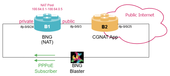
In this subsection, we’ll configure the CGNAT-BNG feature on router B1. We assume, that you are familiar with PPPoE or IPoE configuration already.
On router B1, configure a PPPoE subscriber management on the interface to the Linux server (e.g., ifp-0/0/24). For sake of simplicity, configure no authentication. As the primary focus is NAT, configuring IPv4-only is sufficient (e.g., NAT pool of 10.1.101.0/24). Also make sure, that B1 has a route to B2 and vice versa.
Click to reveal the answer
cfg> set access aaa-profile AUTH_PROFILE authentication order NONE
cfg> set access access-profile PPPOE_ACCESS instance default
cfg> set access access-profile PPPOE_ACCESS protocol pppoe enable true
cfg> set access access-profile PPPOE_ACCESS protocol ppp lcp authentication-protocol PAP_CHAP
cfg> set access access-profile PPPOE_ACCESS protocol ppp ipcp enable true
cfg> set access access-profile PPPOE_ACCESS protocol ppp ipcp source-ifl lo-0/0/0/0
cfg> set access access-profile PPPOE_ACCESS address-family ipv4 enable true
cfg> set access access-profile PPPOE_ACCESS address-family ipv4 pool-name PPPOE_POOL_IPV4
cfg> set access access-profile PPPOE_ACCESS address-family ipv4 primary-dns 192.168.0.101
cfg> set access access-profile PPPOE_ACCESS address-family ipv4 secondary-dns 192.168.0.102
cfg> set access interface double-tagged ifp-0/0/24 101 101 1 255 access-type PPPoE
cfg> set access interface double-tagged ifp-0/0/24 101 101 1 255 access-profile-name PPPOE_ACCESS
cfg> set access interface double-tagged ifp-0/0/24 101 101 1 255 aaa-profile-name AUTH_PROFILE
cfg> set access pool PPPOE_POOL_IPV4 ipv4-address low 10.1.101.1
cfg> set access pool PPPOE_POOL_IPV4 ipv4-address high 10.1.101.254
cfg> set access pool PPPOE_POOL_IPV4 ipv4-address subnet-mask 255.255.255.255
cfg> commit
We’ve already mentioned that you need to have the right platform profile active to run CGNAT. So, let’s do this first.
On router B1 configure a platform profile that supports NAT in combination with BNG functionality. As we do not want to use QoS, a profile supporting one queue per subscriber is sufficient.
Click to reveal the answer
cfg> set system platform profile nat_1q
cfg> commit
First, we need to define a NAT pool using the set forwarding-options address-translation pool <pool-name> command. If a NAT pool is exhausted, additional pools can simply be defined and daisy-chained using the next-pool option.
On router B1 configure a NAT pool consisting of the address range from 100.64.0.1 to 100.64.0.10
Click to reveal the answer
cfg> set forwarding-options address-translation pool NAT_POOL ipv4-address low 100.64.0.1
cfg> set forwarding-options address-translation pool NAT_POOL ipv4-address high 100.64.0.10
cfg> commit|
The shared address space 100.64.0.0/10 was allocated by IANA for CGNAT deployments. This address block was assigned to avoid operational issues when using RFC 1918 addresses within a service provider network. |
Next, we define a NAT profile with the command set forwarding-options address-translation profile profile-name.
On router B1 create a new NAT profile. The NAT profile should use the NAT pool that was created in the last exercise for public addresses. Also limit the number of NAT rules to 256 and set the ageing-timer for all protocols to 3 minutes.
Click to reveal the answer
cfg> set forwarding-options address-translation profile NAT_PROFILE pool NAT_POOL
cfg> set forwarding-options address-translation profile NAT_PROFILE max-rules 256
cfg> set forwarding-options address-translation profile NAT_PROFILE ip-protocol tcp ageing-timeout 180
cfg> set forwarding-options address-translation profile NAT_PROFILE ip-protocol udp ageing-timeout 180
cfg> set forwarding-options address-translation profile NAT_PROFILE ip-protocol other ageing-timeout 180
cfg> commit
Defining a NAT pool and a NAT profile alone have no effect. To achieve network address translation, we need to define where the translation should take place. NAT rules are defined from the inside interface (also called private or local interface) towards the outside interface (also known as public interface). The CGNAT service then ensures automatically that return traffic is translated accordingly.
The role of an interface can be defined using the set interface <name> unit <unit> address-translation direction command. It is also necessary to enable NAT in the appropriate routing instance using the `set instance default address-translation true command.
On router B1 define the interface towards router B2 as the public interface (e.g., ifp-0/0/3). Also enable address-translation in instance default.
Click to reveal the answer
cfg> set interface ifp-0/0/3 unit 0 address-translation direction public
cfg> set instance default address-translation true
cfg> commit
When configuring NAT in conjunction with BNG functionality, the NAT profile is part of the service definition. Therefore, it’s necessary to create a service profile - if none already exists - with the set access service-profile <profile-name> address-translation profile command. This profile can include additional service definitions, such as class-of-service or HTTP redirect services. This service profile needs to be assigned to an access interface using the set access interface
On router B1 define a service profile that contains the previously NAT profile for address translation. Afterwards apply this service profile to the access interface, i.e., the interface connected to the BNG Blaster (e.g., ifp-0/0/24).
Click to reveal the answer
cfg> set access service-profile SERVICE_PROFILE address-translation profile NAT_PROFILE
cfg> set access interface double-tagged ifp-0/0/24 101 101 1 255 service-profile-name SERVICE_PROFILE
cfg> commit|
The access service profile is apply to subscriber during session establishment. Configuring a new service profile, does not affect existing subscriber sessions. Subscriber need to disconnect and re-connect in order to get the new services. |
Now, that we have completed all configuration steps, we can use the BNG Blaster to generate a few PPPoE sessions and monitor the NAT operation.
Let’s first check whether subscriber sessions were successfully established and which IPv4 addresses were allocated to them:
cfg> show subscriber
Subscriber-Id           Interface         VLAN       Type    State
72339069014638604       ifp-0/0/24        101:1      PPPoE   ESTABLISHED
72339069014638605       ifp-0/0/24        101:2      PPPoE   ESTABLISHED
72339069014638606       ifp-0/0/24        101:3      PPPoE   ESTABLISHED
72339069014638607       ifp-0/0/24        101:4      PPPoE   ESTABLISHED
72339069014638608       ifp-0/0/24        101:5      PPPoE   ESTABLISHED
<...>
cfg> show subscriber pool summary
Pool Name                        AFI  Usage           Range
PPPOE_POOL_IPV4                  IPv4 10/254          10.1.101.1 - 10.1.101.254
In this example, ten PPPoE sessions are active and addresses were taken from the 10.1.100.0/24 address pool. Next, we can check the NAT pool:
cfg> show address-translation allocation pool
Pool: NAT_POOL
  Instance: default
  Allocated: 0.05%

cfg> show address-translation allocation user
User                             Original Address     Translated Address   Port Range
ppp-0/0/24/72339069014638604     10.1.101.11          100.64.0.5            1024 - 1055
ppp-0/0/24/72339069014638605     10.1.101.12          100.64.0.4            1024 - 1055
ppp-0/0/24/72339069014638606     10.1.101.13          100.64.0.3            1024 - 1055
ppp-0/0/24/72339069014638607     10.1.101.14          100.64.0.2            1024 - 1055
ppp-0/0/24/72339069014638608     10.1.101.15          100.64.0.1            1024 - 1055
<...>
cfg> show address-translation allocation user ppp-0/0/24/72339069014638604
User: ppp-0/0/24/72339069014638604 Profile: NAT_PROFILE Instance: default
  Pool: NAT_POOL
  Original Address: 10.1.101.11        Translated Address: 100.64.0.5
  Port Range: 1024 - 1055              Port Range Index: 0
  Allocated:
    tcp: 0/32 (0.00%)
    udp: 1/32 (3.12%)
    other: 1/32 (3.12%)
The show address-translation allocation can be used to list all NAT pools and track how many resources from each pool are already consumed. The command can also be used to lists the public IP addresses and port ranges allocated to the PPPoE subscribers.
Finally, the active translation rules can be display using the show address-translation rule command.
cfg> show address-translation rule
Instance: default
User Protocol Original Address Translated Address Direction
ppp-0/0/24/72339069014638604 udp 10.1.101.11, 65056 100.64.0.5, 1024 Both
ppp-0/0/24/72339069014638605 udp 10.1.101.12, 65056 100.64.0.4, 1024 Both
ppp-0/0/24/72339069014638606 udp 10.1.101.13, 65056 100.64.0.3, 1024 Both
ppp-0/0/24/72339069014638607 udp 10.1.101.14, 65056 100.64.0.2, 1024 Both
ppp-0/0/24/72339069014638608 udp 10.1.101.15, 65056 100.64.0.1, 1024 Both
<....>
cfg> show address-translation rule user ppp-0/0/24/72339069014638611
Instance: default
User Protocol Original Address Translated Address Direction
ppp-0/0/24/72339069014638611 udp 10.1.101.18, 65056 100.64.0.10, 1024 Both
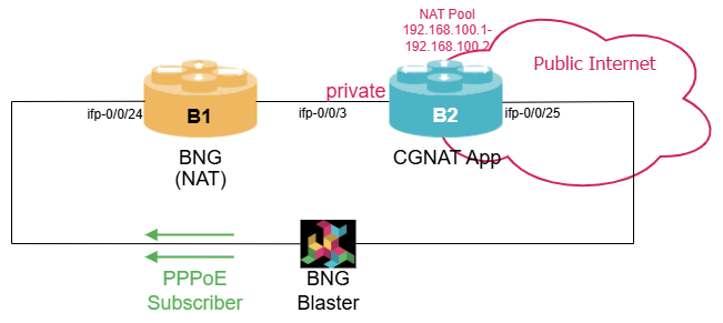
ppp-0/0/24/72339069014638611 icmp 10.1.101.18, 256 100.64.0.10, 1024 BothConfiguring CGNAT Appliance
In this subsection, we shift our focus to the CGNAT standalone feature, which we’ll configure on router B2.
Again, we need to make sure that we have the right platform profile active to run CGNAT.
On router B2 configure a platform profile that supports NAT standalone functionality.
Click to reveal the answer
cfg> set system platform profile nat_standalone
cfg> commit
The initial configuration steps are similar to the CGNAT-BNG use case, so we can go through them quickly. The following exercise serves as a repetition.
On router B2 configure a NAT Pool with address range from 192.168.100.1 to 192.168.100.2 and a NAT profile. The maximum number of rules should be set to 1024 and the ageing timer for all protocols to 3 minutes.
Click to reveal the answer
cfg> set forwarding-options address-translation pool NAT_POOL ipv4-address low 192.168.100.1
cfg> set forwarding-options address-translation pool NAT_POOL ipv4-address high 192.168.100.2
cfg> set forwarding-options address-translation profile NAT_PROFILE pool NAT_POOL
cfg> set forwarding-options address-translation profile NAT_PROFILE max-rules 1024
cfg> set forwarding-options address-translation profile NAT_PROFILE ip-protocol tcp ageing-timeout 180
cfg> set forwarding-options address-translation profile NAT_PROFILE ip-protocol udp ageing-timeout 180
cfg> set forwarding-options address-translation profile NAT_PROFILE ip-protocol other ageing-timeout 180
cfg> commit
Enabling NAT in the appropriate routing instance and defining the upstream interfaces as public interfaces is done the same way as in the CGNAT-BNG scenario. When configuring CGNAT in standalone mode, we need to define the private interfaces using the set interface <name> unit <unit> address-translation direction local command. We also need to attach the NAT profile to this interface directly, using the set interface <name> unit <unit> address-translation profile <profile-name> command.
On router B2 configure define the interface towards the Linux server as the public interface (e.g., ifp-0/0/3). Also enable address-translation in instance default. Configure the interface connecting to router B1 as local interface and attach the NAT profile to it.
Click to reveal the answer
cfg> set instance default address-translation true
cfg> set interface ifp-0/0/25 unit 0 address-translation direction public
cfg> set interface ifp-0/0/3 unit 0 address-translation direction local
cfg> set interface ifp-0/0/3 unit 0 address-translation profile NAT_PROFILE
cfg> commit
If the BNG Blaster is still running and generating traffic, we can verify the correct translation with the usual commands:
cfg> show address-translation rule
Instance: default
User                             Protocol   Original Address        Translated Address      Direction
ifl-0/0/3/0                      udp        100.64.0.1, 1024        192.168.102.1, 1056     Both
ifl-0/0/3/0                      udp        100.64.0.2, 1024        192.168.102.2, 1056     Both
ifl-0/0/3/0                      udp        100.64.0.3, 1024        192.168.102.6, 1024     Both
ifl-0/0/3/0                      udp        100.64.0.4, 1024        192.168.102.5, 1024     Both
ifl-0/0/3/0                      udp        100.64.0.5, 1024        192.168.102.2, 1024     Both
<....>
The main difference in the output compare to the BNG configuration is that there are no users any more. Thus the local interface is listed as user.
Configuring Static NAT
So far, we’ve demonstrated how to configure dynamic NAT, which is the most common scenario. However, in some cases, it is useful to create static NAT rules to ensure that a specific source IP address and source port are always translated to the same address and port combination on the public network. The configuration process for static NAT is the same for both CG-NAT BNG and standalone NAT.
Static NAT is configured by creating a NAT rule using the set forwarding-options address-translation rule <rule-name> command. A static NAT rule can include multiple mappings, each defined using an ordinal and an ordinal number. For each ordinal, you need to specify the routing instance to which it applies. You must also define the protocol, for instance UDP, followed by the private or local IP address and the local port. This local address port combination is then translated to the public IP address and port specified in the ordinal.
On router B2 configure a static NAT rule that translates UDP traffic from IPv4 address 100.64.0.3 and port 1056 to the public IPv4 address 192.168.100.10 and UDP port 4321.
Click to reveal the answer
cfg> set forwarding-options address-translation rule DEMO_RULES ordinal 1 instance default
cfg> set forwarding-options address-translation rule DEMO_RULES ordinal 1 ip-protocol udp
cfg> set forwarding-options address-translation rule DEMO_RULES ordinal 1 local ipv4-address 100.64.0.3
cfg> set forwarding-options address-translation rule DEMO_RULES ordinal 1 local port 1056
cfg> set forwarding-options address-translation rule DEMO_RULES ordinal 1 public ipv4-address 192.168.100.10
cfg> set forwarding-options address-translation rule DEMO_RULES ordinal 1 public port 4321
cfg> commit
After committing the configuration, you can verify that the static rule has been added by running the show address-translation rule command. The output will reflect the static mapping we just created. You can also see that the static NAT rule is not bound to a specific interface, but acts globally.
cfg> show address-translation rule
Instance: default
User                             Protocol   Original Address        Translated Address      Direction
ifl-0/0/3/0                      udp        100.64.0.1, 1024        192.168.102.1, 1056     Both
ifl-0/0/3/0                      udp        100.64.0.2, 1024        192.168.102.2, 1056     Both
static                           udp        100.64.0.3, 1024        192.168.102.10, 4321    Both
ifl-0/0/3/0                      udp        100.64.0.4, 1024        192.168.102.5, 1024     Both
ifl-0/0/3/0                      udp        100.64.0.5, 1024        192.168.102.2, 1024     Both
<...>
Monitoring CGNAT Operation
We’ve already seen some commands to monitor the NAT pool allocation and translation rules. To complete this module, we want to provide a few additional commands that might be useful to track platform resources:
cfg> show address-translation trap statistics
Protocol   Flags                     Status             Count
tcp        -|syn|-|-|-|-|-|-|-       Success               20
tcp        fin|-|-|-|ack|-|-|-|-     Success               30
tcp        -|syn|-|-|ack|-|-|-|-     Success               15
udp        -|-|-|-|-|-|-|-|-         Success              434
other      -|-|-|-|-|-|-|-|-         Success            10332
Total Successful Traps:                                 10831
Total Failed Traps:                                         0

cfg> show address-translation blocked-port
Protocol     Port Number
udp                 4789
udp                 4790
udp                 6081

cfg> show address-translation platform-resource
Resource Type: NAT_EXTERNAL_TO_INTERNAL
  Estimated Entries: 267710
  Consumed Entries: 10
Resource Type: NAT_INTERNAL_TO_EXTERNAL
  Estimated Entries: 267710
  Consumed Entries: 10