Configuring LDP-based Virtual Private Wire Service
Module Introduction
Before you start the hands-on part of this module, you should load the appropriate configuration and verify that the testbed is up and running by executing the corresponding robot file:
student@tour:~/trainings_resources/robot$ robot mpls_ldp_pw/mpls_ldp_pw_setup.robot|
We use IS-IS as IGP for the examples and exercises in this module. The choice of IGP is not important for understanding and configuration of LDP-based VPWS. However, if you prefer to run OSPF instead, you can alternatively load the setup using the |
In order to get a better understanding, the lab setup is shown in the picture below.
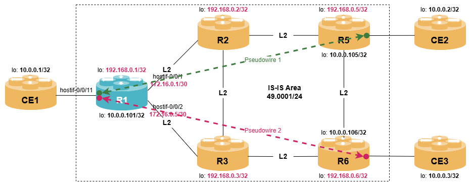
|
In RBFS version 26.1.1, LDP-based pseudowire service is only supported on Q2A/Q2C/QAX-based platforms, but not in virtual environments. In this module, the configuration steps are explained and the corresponding control plane outputs are shown. However, the data plane is working due to missing support in VPP. |
Virtual Private Wire Service
In module Configuring EVPN Virtual Private Wire Service, we defined a Virtual Private Wire Service (VPWS) using EVPN-based pseudowires. In this module, we present an alternative approach that uses Label Distribution Protocol instead of BGP as the signaling protocol to establish and maintain pseudowires.
An LDP pseudowire enables service providers to emulate a point-to-point Layer 2 connection over an MPLS network. These pseudowires are built on top of the existing MPLS infrastructure and use extensions to LDP to signal and maintain virtual circuits between PE routers. For pseudowire setup, LDP relies on a targeted LDP session, where the TCP session is established between the two PEs using loopback addresses, i.e., the LDP neighbors do not have to be directly connected to each other.
Additionally, RFC 4447 introduces two new FEC elements: the pseudowire ID FEC element and the generalized pseudowire ID FEC element, which help the PE routers identify the endpoints of a pseudowire.
-
The pseudowire ID FEC (FEC 128) element is used when both pseudowire endpoints are provisioned with the same 32-bit pseudowire identifier, along with the the encapsulation type and the interface parameter sub-TLV which is also defined in RFC 4447. It’s typically employed in static configurations where the pseudowire ID is known in advance.
-
The generalized pseudowire ID FEC (FEC 129) element allows dynamic discovery and setup of pseudowires based on the pair of endpoints, without the need for a preconfigured pseudowire ID. This approach supports autodiscovery and is ideal for automated provisioning in larger or more flexible network environments.
As a pseudowire is a point-to-point connection, it links two entities together. These endpoints are referred to as attachment circuits and represent the Ethernet interfaces connected to the CE device. The attachment circuit may either be an Ethernet port or a dedicated VLAN on an Ethernet port. Note that while the concept of pseudowires applies to other layer-2 technologies like ATM or Frame Relay, we will focus on Ethernet, as modern white-box switches typically only support Ethernet interfaces.
Once a pseudowire is configured and associated with an attachment circuit, the PE routers exchange LDP Label Mapping messages across the targeted LDP session that has been previously set up. An LDP Label Mapping message contains an FEC TLV, a Label TLV, and optional parameter TLVs. Typically, each FEC TLV consists of a set of FEC elements. However, for pseudowire setup and maintenance, the FEC TLV will contain exactly one FEC element.
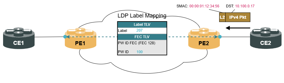
In our example, the pseudowire is configured with a static pseudowire ID of 100 on both sides. Therefore, the PE routers use FEC 128, which includes the pseudowire ID. The LDP Label Mapping message also contains the Label TLV, which advertises the MPLS label that identifies the pseudowire and the label that the remote PE router needs to push onto the label stack.
The PW label bindings are distributed using LDP’s downstream unsolicited mode, meaning that the PE routers advertise the label to the remote PE router without waiting for a specific request from the downstream router.
When two PE routers have established a pseudowire, Ethernet traffic can be carried across the MPLS core network. An Ethernet frame—either untagged or tagged—is received on an incoming interface associated with the pseudowire. The local PE router pushes the pseudowire label, learned from the remote PE router, onto the frame and extracts the next-hop information, which is recursively looked up in the routing table, resulting in the pushing of a transport label. The frame is then forwarded to the next router along the LSP towards the downstream PE router.
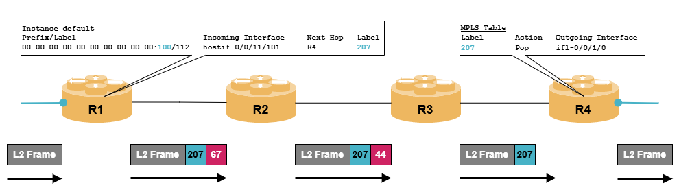
Transit P routers are not aware of the VPWS and thus only act on the transport label, either swapping it or performing penultimate hop popping. The egress PE router receives a frame containing only the PW label. It will perform an MPLS lookup, which results in forwarding the packet to the attachment circuit.
LDP Pseudowire Configuration
In order to configure LDP-based pseudowires in RBFS, you must first set up an MPLS core network. You can choose any IGP or MPLS signaling protocol. Just because we are using LDP for pseudowire setup doesn’t mean you need to use LDP to establish LSPs as well—although there is some synergy. Before diving into the details, let’s go over a quick checklist.
-
Configure IGP (OSPF or IS-IS)
-
Configure MPLS signaling protocol to setup LSPs (e.g., LDP, segment routing)
-
Setup targeted LDP session between PE routers (optionally add TCP authentication)
-
Enable
l2vpn vpls-vpwsaddress family in the appropriate routing instance and in LDP -
Configure attachment circuit, i.e., interface connecting to CE device
-
Configure pseudowire using a shared pseudowire ID
Configure a targeted LDP session to router R5 (192.168.0.5) and R6 (192.168.0.6); there is no need for authentication. (Quick tip: you can find the instructions in Label Distribution Protocol (LDP)).
In addition, enable the l2vpn vpls-vpws address-family at the instance default level as well as the LDP level.
Click to reveal the answer
set instance default protocol ldp targeted-neighbor ipv4 192.168.0.5 192.168.0.1
set instance default protocol ldp targeted-neighbor ipv4 192.168.0.6 192.168.0.1
set instance default address-family l2vpn vpls-vpws
set instance default protocol ldp address-family l2vpn vpls-vpws status enable
commit
We can now verify the targeted LDP sessions are operational:
supervisor@R1>rtbrick: cfg> show ldp session
Instance: default
  LDP ID            Peer IP                   State             Up/Down           FECRcvd   FECSent
  192.168.0.2:0     192.168.0.2               Operational       0d:00h:00m:16s          5         5
  192.168.0.3:0     192.168.0.3               Operational       0d:00h:00m:16s          5         5
  192.168.0.5:0     192.168.0.5               Operational       0d:00h:00m:19s          6         5
  192.168.0.6:0     192.168.0.6               Operational       0d:00h:00m:22s          6         5
Now that we have a targeted LDP session up and running between the PE routers, we need to configure the attachment circuit. Since the attachment circuit is a Layer 2 interface that sends and receives frames without inspecting their content, there’s no need to configure an IP address. Instead, the interface-type must be set to l2vpn-vpws.
Interface hostif-0/0/11 is used to connect router R1 to CE1. Configure two VLANs 101 and 102 on this interface and set the interface-type of the appropriate interfaces to l2vpn-vpls.
Click to reveal the answer
delete interface hostif-0/0/11 admin-status down
set interface hostif-0/0/11 description "Link to CE1"
set interface hostif-0/0/11 unit 101 interface-type l2vpn-vpws
set interface hostif-0/0/11 unit 101 vlan 101
set interface hostif-0/0/11 unit 102 interface-type l2vpn-vpws
set interface hostif-0/0/11 unit 102 vlan 102
commit
Verification:
cfg> show interface logical
Interface              Instance            Admin   Link    Oper    Outer VLAN   Inner VLAN  IPv4 Status,MTU   IPv6 Status,MTU   Type
lo-0/0/0/0             default             Up      Up      Up      -            -           Up,NA             Down,NA           l3
hostif-0/0/1/0         default             Up      Up      Up      -            -           Up,1500           Down,1500         l3
hostif-0/0/2/0         default             Up      Up      Up      -            -           Up,1500           Down,1500         l3
hostif-0/0/11/101      default             Up      Up      Up      101          -           -                 -                 l2vpn-vpws
hostif-0/0/11/102      default             Up      Up      Up      102          -           -                 -                 l2vpn-vpws
In this example, we have configured two single-tagged attachment circuits. RBFS also supports untagged and double-tagged attachment circuits.
|
In case of complex setups, RBFS allows the manipulation of VLAN identifiers on both ends of a pseudowire using the |
The pseudowire definition is configured under the set instance <instance> protocol ldp vpls-vpws command hierarchy, associating the local attachment circuit with the unique pseudowire ID and the remote PE router.
Configure two LDP-based pseudowires connecting interface hostif-0/0/11 VLAN 101 with router R5 (PW ID 101) and VLAN 102 with router R6 (PW ID 102).
Click to reveal the answer
set instance default protocol ldp vpls-vpws interface hostif-0/0/11/101 pseudowire-id 101
set instance default protocol ldp vpls-vpws interface hostif-0/0/11/101 neighbor ipv4 address 192.168.0.5
set instance default protocol ldp vpls-vpws interface hostif-0/0/11/102 pseudowire-id 102
set instance default protocol ldp vpls-vpws interface hostif-0/0/11/102 neighbor ipv4 address 192.168.0.6
commit
We can verify that the pseudowires are established. The prefix is display in BGP EVPN style. The most important part is the PW ID.
cfg> show ldp l2vpn pseudowire
Instance: default, AFI: l2vpn, SAFI: vpls-vpws
  Number of local interfaces: 2
    Peer IP                                       Interface Name       Prefix                                       Status              PW ID
    192.168.0.5                                   hostif-0/0/11/101    00.00.00.00.00.00.00.00.00.00:101/112        Up                    101
    192.168.0.6                                   hostif-0/0/11/102    00.00.00.00.00.00.00.00.00.00:102/112        Up                    102
 |
cfg> show ldp l2vpn pseudowire detail
Instance: default, AFI: l2vpn, SAFI: vpls-vpws, Number of local interfaces: 2
  Prefix: 00.00.00.00.00.00.00.00.00.00:101/112
    Peer IP: 192.168.0.5, Interface name: hostif-0/0/11/101
    Pop label: label:519936, Push label: label:524032, Status: Up
    Pseudowire ID: 101, Control word: False
  Prefix: 00.00.00.00.00.00.00.00.00.00:102/112
    Peer IP: 192.168.0.6, Interface name: hostif-0/0/11/102
    Pop label: label:519941, Push label: label:519936, Status: Up
    Pseudowire ID: 102, Control word: False
Further we can confirm that the LDP pseudowire is installed into the RBFS routing table.
cfg>  show route l2vpn vpls-vpws
Flags: & - Imported
Instance: default, AFI: l2vpn, SAFI: vpls-vpws
Flags  Prefix/Label                                  Incoming Interface     Source   Next Hop                            Label          Outgoing Interface
       00.00.00.00.00.00.00.00.00.00:101/112         hostif-0/0/11/101      ldp      192.168.0.5                         524032,519939  hostif-0/0/1/0
       00.00.00.00.00.00.00.00.00.00:102/112         hostif-0/0/11/102      ldp      192.168.0.6                         519936,524037  hostif-0/0/2/0

cfg> show route l2vpn vpls-vpws detail
Instance: default, AFI: l2vpn, SAFI: vpls-vpws
  Prefix: 00.00.00.00.00.00.00.00.00.00:101/112
    Source: ldp, Preference: 190
      Next Hop: 192.168.0.5
        Covering prefix: 192.168.0.5/32
        Next Hop type: Vpws Remote ingress cross connect, Next Hop action: mpls label push
        Resolved in: default-ipv4-labeled-unicast(Primary)
        Incoming interface: hostif-0/0/11/101, Incoming Interface MAC: 7a:56:0c:c0:00:01
        Outgoing Interface: hostif-0/0/1/0, NextHop MAC: 7a:78:e5:c0:00:01
        MPLS-Label: 524032, 519939
  Prefix: 00.00.00.00.00.00.00.00.00.00:102/112
    Source: ldp, Preference: 190
      Next Hop: 192.168.0.6
        Covering prefix: 192.168.0.6/32
        Next Hop type: Vpws Remote ingress cross connect, Next Hop action: mpls label push
        Resolved in: default-ipv4-labeled-unicast(Primary)
        Incoming interface: hostif-0/0/11/102, Incoming Interface MAC: 7a:56:0c:c0:00:01
        Outgoing Interface: hostif-0/0/2/0, NextHop MAC: 7a:0a:71:c0:00:02
        MPLS-Label: 519936, 524037
Control Word
The control word, defined in RFC 4385, is an optional 32-bit field inserted between the MPLS label stack and the Layer 2 payload. Its primary purpose is to prevent misinterpretation of the payload as an IP header by MPLS core routers, and it also helps detect packet misordering. The usage of the control word must be negotiated and agreed upon during signaling. The control word is an optional step in the pseudowire configuration. By default, the use of control word is disabled.
For both LDP-based pseudowires (PW ID 101 and 102), enable the use of control word.
Click to reveal the answer
set instance default protocol ldp vpls-vpws interface hostif-0/0/11/101 control-word enable
set instance default protocol ldp vpls-vpws interface hostif-0/0/11/102 control-word enable
commit
We can now check that the pseudowire is configure with control-word enabled:
cfg> show ldp l2vpn pseudowire detail
Instance: default, AFI: l2vpn, SAFI: vpls-vpws, Number of local interfaces: 2
  Prefix: 00.00.00.00.00.00.00.00.00.00:101/112
    Peer IP: 192.168.0.5, Interface name: hostif-0/0/11/101
    Pop label: label:519936, Push label: label:524032, Status: Up
    Pseudowire ID: 101, Control word: True                        (1)
  Prefix: 00.00.00.00.00.00.00.00.00.00:102/112
    Peer IP: 192.168.0.6, Interface name: hostif-0/0/11/102
    Pop label: label:519941, Push label: label:519936, Status: Up
    Pseudowire ID: 102, Control word: True                        (1)

<...>| 1 | Control word is enabled. |