OSPF Single-Area Networks
Module Introduction
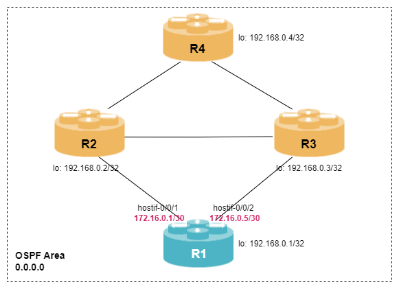
Before you start the hands-on part of this module, you should load the appropriate configuration and verify that the testbed is up and running by executing the corresponding robot file:
student@tour:~/trainings_resources/robot$ robot ospf_single_area/ospf_single_area_setup.robotIn order to get a better understanding, the lab setup is shown in the picture below.
OSPF Overview
Open Shortest Path First (OSPF) is a link-state routing protocol designed to find the best path within an IP network. The term open is used to indicate that the Dijkstra Shortest Path First (SPF) algorithm, which is used to construct the topology and routing table, is not proprietary to any vendor. OSPF is used within an autonomous system and is thus classified as an interior gateway protocol (IGP). It has proven to be a very scalable routing protocols, supporting tens of thousands of nodes.
Since its original IETF specification, OSPF has evolved and been enhanced through several RFCs. Currently, there are two versions in use: version 2, defined in RFC 2328 for IPv4 networks, and version 3 for IPv6 networks, defined in RFC 5340.
OSPF uses five different packet types to establish and maintain OSPF neighborship and exchange routing information:
-
Hello packets
-
Database Description packets
-
Link State Request packets
-
Link State Update packets
-
Link State Acknowledgment packets
OSPF Neighbors
Establishing OSPF Neighborship
OSPF routers establish neighborships with each other to exchange routing information, ensuring the consistency and accuracy of their link-state databases. OSPF routers use a Hello protocol to discover OSPF neighbors and establish adjacencies with them. The Hello protocol involves the exchange of Hello packets over OSPF-enabled interfaces. Routers periodically send Hello packets to monitor the status of existing neighbors.
Hello packets contain various essential pieces of information, including:
-
OSPF Router ID of the originating router
-
OSPF area ID
-
Subnet mask of the interface on which the Hello packet is sent
-
OSPF network type
-
Hello and Dead timers
-
Authentication type and authentication key
-
Router priority
-
Designated router (DR) and backup designated router (BDR)
-
a list of recognized OSPF neighbors on the particular interface
When two routers on a network send and receive Hello packets, they first check whether the information in the Hello packets received matches specific criteria, i.e., the attributes marked in the list above must match.
|
OSPF supports five different network types, with the most important ones being point-to-point (p2p) and broadcast. In broadcast networks, such as Ethernet, Hello packets are sent to the All OSPF Routers multicast address (224.0.0.5), and a designated router (DR) and backup designated router (BDR) are elected. Once the DR and BDR are elected, all other OSPF routers will form an OSPF neighborship only with the DR and BDR and will send routing updates to a multicast address dedicated to DR and BDR only (224.0.0.6). Point-to-point networks were originally developed for PPP and Frame Relay but are also used in modern networks for high-speed Ethernet interfaces. The advantage of using the p2p mode is that no DR and BDR are elected. |
Once the Hello packet checks are successful, the routers go through a series of state transitions:
-
Down state is the initial state before neighbors are discovered, indicating that no Hello packets were received within the dead time interval.
-
Init state indicates that a Hello packet has been received, and the process to establish a neighbor relationship has begun.
-
2-way state indicates that a router has identified its own router ID in the neighbor list of the Hello packet received from the peer. At this point, the negotiation of the Designated Router (DR) and Backup Designated Router (BDR) takes place if necessary.
-
Exstart state is used to prepare for the exchange of database description packets by negotiating the initial sequence numbers for link-state advertisements.
-
Exchange state is used to exchange database description packets that provide information about the entire link-state database.
-
Loading state indicates that specific missing link-state advertisements are requested because they are absent from the link-state database.
-
Full state represents OSPF neighbors that have successfully synchronized their Link-State Databases.
If a router does not receive Hello packets from its neighbor within the configured Dead timer interval, it assumes the neighbor is no longer reachable, and the neighbor relationship is torn down again.
Configuring OSPF Neighbors
Now that we have understand the basic concept of OSPF Hello protocol, let’s configure the OSPF neighbors using the set instance <instance> protocol ospf address-family ipv4 area <area-id> syntax.
Configure OSPF protocol in instance default with area 0.0.0.0 and include the interfaces hostif-0/0/1/0, hostif-0/0/2/0 and lo-0/0/0/0 in the configuration. Set the network-type of the interfaces to point-to-point.
How many OSPF neighbors can you see?
Click to reveal the answer
cfg> set instance default protocol ospf address-family ipv4 router-id 192.168.0.1
cfg> set instance default protocol ospf address-family ipv4 area 0.0.0.0 interface hostif-0/0/1/0
cfg> set instance default protocol ospf address-family ipv4 area 0.0.0.0 interface hostif-0/0/1/0 network-type p2p
cfg> set instance default protocol ospf address-family ipv4 area 0.0.0.0 interface hostif-0/0/2/0
cfg> set instance default protocol ospf address-family ipv4 area 0.0.0.0 interface hostif-0/0/2/0 network-type p2p
cfg> set instance default protocol ospf address-family ipv4 area 0.0.0.0 interface lo-0/0/0/0
cfg> commit
cfg> show ospf neighbor
Instance: default, Address family: ipv4
  Address                        Interface            Router          Area            State      Priority  DR              BDR             Uptime          Expires
  172.16.0.2                     hostif-0/0/1/0       192.168.0.2     0.0.0.0         Init       1         0.0.0.0         0.0.0.0         never           37s
  172.16.0.6                     hostif-0/0/2/0       192.168.0.3     0.0.0.0         Init       1         0.0.0.0         0.0.0.0         never           37s
There are two neighboring OSPF routers, but the neighborships are stuck in Init state.
The command show ospf neighbor provides a list of all detected neighbors:
cfg> show ospf neighbor
Instance: default, Address family: ipv4
  Address                        Interface            Router          Area            State      Priority  DR              BDR             Uptime          Expires
  172.16.0.2                     hostif-0/0/1/0       192.168.0.2     0.0.0.0         Init       1         0.0.0.0         0.0.0.0         never           37s
  172.16.0.6                     hostif-0/0/2/0       192.168.0.3     0.0.0.0         Init       1         0.0.0.0         0.0.0.0         never           37s
We can see that there are OSPF neighbors, but both are stuck in the Init state. This indicates that the routers are sending and receiving Hello packets, but are unable to progress further in the adjacency process. So, what’s the issue? Let’s inspect the Hello packets to see if we can find any clues.
cfg> show ospf interface hostif-0/0/1/0
Instance: default
  Interface            Area            IP Address      State          Type       Cost     Priority DR              BDR             MTU
  hostif-0/0/1/0       0.0.0.0         172.16.0.1      P2P            p2p        10000    1        0.0.0.0         0.0.0.0         1500
cfg> show ospf interface hostif-0/0/1/0 detail
Instance: default
  Interface: hostif-0/0/1/0, Area: 0.0.0.0
    State: P2P, Type: p2p, Primary IPv4: 172.16.0.1, Router priority: 1
    Designated router: 0.0.0.0, Backup designated router: 0.0.0.0
    Hello interval: 10, Router dead interval: 40, Wait timer: 40
    Metric: 10000, IPv4 MTU: 1500, Auth type: none
    Capabilities: *|-|-|-|-|-|E|*
    Received messages:
      Hello: 0, Data descriptor: 0, LS request: 0       (1)
      LS update: 0, LS acknowledgement: 0
    Sent messages:
      Hello: 11, Data descriptor: 0, LS request: 0      (2)
LS update: 0, LS acknowledgement: 0| 1 | The local device does not receive any OSPF Hello messages. |
| 2 | The local router sends OSPF Hello packets. |
Let’s turn on packet capture on this interface and see if there is any packet incoming:
cfg> capture interface hostif-0/0/1/0 direction both
Success : ifl capture started

<...>
2023-10-17T05:12:27.014077+0000 7a:77:1f:c0:00:01 > 01:00:5e:00:00:05, ethertype IPv4 (0x0800), length 78: (tos 0xc0, ttl 1, id 28, offset 0, flags [none], proto OSPF (89), length 64)
    172.16.0.1 > 224.0.0.5: OSPFv2, Hello, length 44
        Router-ID 192.168.0.1, Backbone Area, Authentication Type: none (0)     (1)
        Options [External]
          Hello Timer 10s, Dead Timer 40s, Mask 255.255.255.252, Priority 1
          Designated Router 172.16.0.1

2023-10-17T05:12:32.046463+0000 7a:fc:da:c0:00:01 > 01:00:5e:00:00:05, ethertype IPv4 (0x0800), length 94: (tos 0xc0, ttl 1, id 109, offset 0, flags [none], proto OSPF (89), length 80)
    172.16.0.2 > 224.0.0.5: OSPFv2, Hello, length 44
        Router-ID 192.168.0.2, Backbone Area, Authentication Type: MD5 (2)      (2)
        Key-ID: 1, Auth-Length: 16, Crypto Sequence Number: 0x652e17c0
        Options [External]
          Hello Timer 10s, Dead Timer 40s, Mask 255.255.255.252, Priority 1
<...>| 1 | Outgoing Hello packets do not use authentication. |
| 2 | Incoming Hello packets use the authentication type MD5. |
As we can see from the output above, the remote OSPF router uses MD5 authentication to encrypt the hello messages. This is the reason why no Hello packets appear in the interface statistics and thus no OSPF neighborship is established.
In order to enable OSPF authentication in RBFS, you need to create an authentication-profile at the global configuration level, which contains the authentication-type and password. This profile can be attached either at
-
the area-level using the command
set instance <instance> protocol ospf address-family ipv4 area <area> authentication-profile <profile>in case all interfaces share the same authentication key, or -
the interface-level using the command
set instance <instance> protocol ospf address-family ipv4 area <area> interface <iflname> authentication-profile <profile>if different authentication settings are used on different interfaces.
Configure OSPF authentication for interface hostif-0/0/1/0 and hostif-0/0/2/0 using type md5 and password rtbrick. The key-id should be set to 1. Can you see any OSPF neighbors now?
Click to reveal the answer
cfg> set authentication-profile MYOSPFAUTH key 1 type md5
cfg> set authentication-profile MYOSPFAUTH key 1 plain-text rtbrick
cfg> set instance default protocol ospf address-family ipv4 area 0.0.0.0 authentication-profile MYOSPFAUTH
cfg> commit
cfg> show ospf neighbor
Instance: default
  Address         Interface            Router ID       Area            State      Priority  DR              BDR             Uptime          Expires
  172.16.0.2      hostif-0/0/1/0       192.168.0.2     0.0.0.0         Full       1         0.0.0.0         0.0.0.0         0d:00h:01m:16s  40 Seconds
  172.16.0.6      hostif-0/0/2/0       192.168.0.3     0.0.0.0         Full       1         0.0.0.0         0.0.0.0         0d:00h:01m:16s  39 Seconds
OSPF Link-State Database
We have already mentioned that OSPF is a link-state routing protocol, i.e., instead of sending its view of the routing table to its neighbors, OSPF routers generate link-state advertisements (LSAs) whenever something changes. These LSAs then need to be sent to all routers in the OSPF network. This process is called flooding. As a result all OSPF routers have the same information which is stored in the link-state database and used to calculate the routing table using the SPF algorithm.
| Link-state advertisements are carried within link-state update (LSU) packets which can contain multiple LSAs for sake of efficiency. The receipt of a link-state update packet is responded to with an link-state acknowledge packet. |
Router LSA
The OSPF link-state database can be examined using the show ospf database command:
cfg> show ospf database
Instance: default, Area: 0.0.0.0
  Type            Link State ID   Advertising Router          Age        Sequence   Checksum     Cost  Link Count
  Router          192.168.0.1     192.168.0.1                  13      0x80000004     0x23ce        -          5
  Router          192.168.0.2     192.168.0.2                  14      0x80000006     0xbb90        -          7
  Router          192.168.0.3     192.168.0.3                  14      0x80000007     0xc06f        -          7
  Router          192.168.0.4     192.168.0.4                1557      0x80000004     0x57b2        -          5
From the output above, we can identify four entries in the link-state database with type Router. OSPF has a couple of LSA types which we will introduce step-by-step. The most important one is the router LSA (or type-1 LSA). Every router in the OSPF area generates exactly one router LSA. The corresponding LSA ID is set to the router ID of the particular router. The router LSA contains a list of links attached to the OSPF router:
cfg> show ospf database ls-id 192.168.0.1 detail
Instance: default, Area: 0.0.0.0 LSAs
  LSA ID: 192.168.0.1
    Advertising router: 192.168.0.1, LSA type: Router
    Sequence number: 0x80000004, Checksum: 0x23ce, LSA age: 48
    Length: 84, Options: *|-|-|-|-|-|E|*, Flags: -|-|-|-                       (1)
    Number of links: 5
      Link ID: 192.168.0.2                                                     (2)
        Link data: 172.16.0.1, Type: P2P                                       (3)
        Type of service: 0, Metric: 10000
      Link ID: 172.16.0.0
        Link data: 255.255.255.252, Type: Stub
        Type of service: 0, Metric: 10000
      Link ID: 192.168.0.3
        Link data: 172.16.0.5, Type: P2P
        Type of service: 0, Metric: 10000
      Link ID: 172.16.0.4
        Link data: 255.255.255.252, Type: Stub
        Type of service: 0, Metric: 10000
      Link ID: 192.168.0.1
        Link data: 255.255.255.255, Type: Stub
Type of service: 0, Metric: 10000| 1 | The option field describes the capabilities of the router. The E-bit is set to signal that type-5 external LSAs will be accepted. The flags indicate, whether this is an ABR or ASBR. We will come back to these settings later. |
| 2 | Each link is represented by the 32-bit link ID. |
| 3 | Each link has a link type and link data. The content of the link data depends on the link type. |
|
Each interface that does not have an adjacency is considered a stub interface – for instance, the loopback interface. Because point-to-point links are considered unnumbered in OSPF, each point-to-point link is additionally advertised as a stub link. |
The content of the link-state database is used as input for the Dijkstra algorithm to calculate the shortest path from the local router to each OSPF router in the area. The Dijkstra algorithm is based on a metric called link costs and the preferred path is the one with the lowest sum of all costs of outgoing interfaces to the destination.
cfg> show ospf spf result
Instance: default, Area: 0.0.0.0
  Node ID         Type            Cost     Advertising Router  Flags        Neighbor Node         Interface         Nexthop
  192.168.0.1     ROUTER          0        192.168.0.1         -|-|-|-      -                     local             -
  192.168.0.2     ROUTER          10000    192.168.0.2         -|-|-|-      192.168.0.2           hostif-0/0/1/0    172.16.0.2
  192.168.0.3     ROUTER          10000    192.168.0.3         -|-|-|-      192.168.0.3           hostif-0/0/2/0    172.16.0.6
  192.168.0.4     ROUTER          10100    192.168.0.4         -|-|-|-      192.168.0.2           hostif-0/0/1/0    172.16.0.2
                                                                            192.168.0.3           hostif-0/0/2/0    172.16.0.6
cfg> show ospf route
Instance: default, AFI: ipv4, SAFI: unicast
  Prefix                     Area             Type             Cost      Next Hop        Interface
  172.16.0.0/30              0.0.0.0          ospf-direct      10000     n/a             local
  172.16.0.4/30              0.0.0.0          ospf-direct      10000     n/a             local
  172.16.0.8/30              0.0.0.0          intra-area       10100     172.16.0.2      hostif-0/0/1/0
  172.16.0.12/30             0.0.0.0          intra-area       10100     172.16.0.6      hostif-0/0/2/0
                                                                         172.16.0.2      hostif-0/0/1/0
  172.16.0.16/30             0.0.0.0          intra-area       10100     172.16.0.6      hostif-0/0/2/0
  192.168.0.1/32             0.0.0.0          ospf-direct      10000     n/a             local
  192.168.0.2/32             0.0.0.0          intra-area       20000     172.16.0.2      hostif-0/0/1/0
  192.168.0.3/32             0.0.0.0          intra-area       20000     172.16.0.6      hostif-0/0/2/0
  192.168.0.4/32             0.0.0.0          intra-area       20100     172.16.0.6      hostif-0/0/2/0
                                                                         172.16.0.2      hostif-0/0/1/0
Network LSA
The Network LSA or type-2 LSA represents a broadcast network. So far, we have only configured two neighbors that were connected via a point-to-point link. For demonstration purpose, let’s configure an other OSPF neighbor using a broadcast link.
Add the interfaces hostif-0/0/11/0 to your existing OSPF configuration. Keep the default network-type setting as broadcast.
Click to reveal the answer
cfg> set instance default protocol ospf address-family ipv4 area 0.0.0.0 interface hostif-0/0/11/0
cfg> commit
cfg> show ospf neighbor interface hostif-0/0/11/0
Instance: default, Address family: ipv4
  Address         Interface            Router ID       Area            State      Priority  DR              BDR             Uptime          Expires
  172.16.0.22     hostif-0/0/11/0      192.168.0.5     0.0.0.0         Full       1         172.16.0.22     172.16.0.21     0d:00h:01m:10s  35s
After the OSPF adjacency to R5 is active, let’s examine the OSPF interface details.
cfg> show ospf interface hostif-0/0/11/0
Instance: default, Address family: ipv4
  Interface            Area            IP Address           State       Type       Cost     Priority DR              BDR             MTU
  hostif-0/0/11/0      0.0.0.0         172.16.0.21          BDR         broadcast  10000    1        172.16.0.22     172.16.0.21     1500
The interface hostif-0/0/11/0 is operating as a broadcast interface, which is the default OSPF network type. The interface is currently in BDR state. We can also observe that, the DR and BDR field are no longer set to 0.0.0.0.
On broadcast networks, there can be multiple routers connected to the same network segment. To avoid excessive and redundant flooding of link-state advertisements, OSPF introduces the concept of a designated router (DR). The designated router represents the network segment and helps to simplify flooding. There is also a backup designated router (BDR) as standby. The DR and BDR are elected based on the router priority. The router with the highest priority wins. In case of multiple routers having the same priority, the highest router ID is preferred.
|
On a broadcast network, routers only form a full OSPF adjacency to the DR and BDR. All other adjacencies remain in state 2-Way. |
The DR generates a network LSA or type-2 LSA to represent a broadcast networki:
cfg> show ospf database
Instance: default, Address family: ipv4, Area: 0.0.0.0
  Type                      Link State ID   Advertising Router          Age        Sequence   Checksum     Cost
  Router                    192.168.0.1     192.168.0.1                 118      0x80000006     0x7094        -
  Router                    192.168.0.2     192.168.0.2                1371      0x80000004     0xbf8e        -
  Router                    192.168.0.3     192.168.0.3                1370      0x80000004     0xc66c        -
  Router                    192.168.0.4     192.168.0.4                1397      0x80000003     0x59b1        -
  Router                    192.168.0.5     192.168.0.5                 119      0x80000003     0xa744        -
  Network                   172.16.0.22     192.168.0.5                 119      0x80000001     0xed55        -

cfg> show ospf database ls-type network detail
Instance: default, Address family: ipv4, Area: 0.0.0.0 LSAs
  LSA ID: 172.16.0.22                                                          (1)
    Advertising router: 192.168.0.5, LSA type: Network, Router ID: 192.168.0.5
    Sequence number: 0x80000001, Checksum: 0xed55, LSA age: 141s
    Interface: hostif-0/0/11/0, Neighbor address: 172.16.0.22
    Length: 32, Options: *|-|-|-|-|-|E|*
    Mask: 255.255.255.252, Number of links: 2
Attached routers: 192.168.0.1, 192.168.0.5 (2)| 1 | The link state ID for a network LSA is the interface IP address of the designated router. |
| 2 | The network LSA contains a list of all attached routers. |
Increase the router-priority on hostif-0/0/11/0 to 100. How does the DR and BDR status change?
Click to reveal the answer
cfg> set instance default protocol ospf address-family ipv4 area 0.0.0.0 interface hostif-0/0/11/0 router-priority 100
cfg> commit
cfg> show ospf interface hostif-0/0/11/0
Instance: default, Address family: ipv4
  Interface            Area            IP Address           State       Type       Cost     Priority DR              BDR             MTU
  hostif-0/0/11/0      0.0.0.0         172.16.0.21          BDR         broadcast  10000    100      172.16.0.22     172.16.0.21     1500
Although, the router priority is now correctly set to 100, R1 remains in state BDR. This is because OSPF’s designated router election process is non-preemptive - once a designated router is elected, it retains the role until it fails or is manually reset. In practice, the first router to come online usually becomes the designated router.
Configuring Link Costs
By default, the metric of all OSPF interfaces in RBFS is set to 10000. Usually, you want to modify these value in order to steer traffic in your network, e.g., preferring high-speed links over low-speed links. The link metric can be modified on a per-interface basis.
Configure the link cost (metric) to be 100 for hostif-0/0/1/0 and hostif-0/0/2/0 and verify the result.
Click to reveal the answer
cfg> set instance default protocol ospf address-family ipv4 area 0.0.0.0 interface hostif-0/0/1/0 metric 100
cfg> set instance default protocol ospf address-family ipv4 area 0.0.0.0 interface hostif-0/0/2/0 metric 100
cfg> commit
cfg> show ospf spf result node-id 192.168.0.4
Instance: default, Area: 0.0.0.0
  Node ID         Type            Cost     Advertising Router  Flags        Neighbor Node         Interface         Nexthop
  192.168.0.4     ROUTER          200      192.168.0.4         -|-|-|-      192.168.0.2           hostif-0/0/1/0    172.16.0.2
                                                                            192.168.0.3           hostif-0/0/2/0    172.16.0.6
Redistribution and External LSAs
OSPF will advertise only link states of OSPF-enabled interfaces, by default. If you have other routing sources, e.g., direct routes or static routes, OSPF allows you to distribute this information as part of an external LSA (or type-5 LSA). A OSPF router that inject an external LSA into the OSPF network is called an Autonomous System Boundary Router (ASBR).
Configure a static route in instance default for destination 172.16.100.0/24 pointing to interface null0 and then redistribute it using the command set instance default protocol ospf address-family ipv4 redistribute static.
Click to reveal the answer
cfg> set instance default static route ipv4 172.16.100.0/24 unicast DISCARD
cfg> set instance default static nexthop-profile DISCARD exit-interface null0
cfg> set instance default protocol ospf address-family ipv4 redistribute static
cfg> commit
Now, let’s have a look at the OSPF database again:
cfg> show ospf database
Instance: default, Area: 0.0.0.0
  Type            Link State ID   Advertising Router          Age        Sequence   Checksum     Cost  Link Count
  Router          192.168.0.1     192.168.0.1                  10      0x80000006     0x2b0e        -          5
  Router          192.168.0.2     192.168.0.2                 335      0x80000006     0xbb90        -          7
  Router          192.168.0.3     192.168.0.3                 335      0x80000007     0xc06f        -          7
  Router          192.168.0.4     192.168.0.4                  78      0x80000005     0x55b3        -          5
Instance: default
  Type            Link State ID   Advertising Router          Age        Sequence   Checksum     Cost  Link Count
  External        172.16.100.0    192.168.0.1                   5      0x80000001     0x8b3f 16777214          -
cfg> show ospf database ls-id 172.16.100.0 detail
Instance: default LSAs
  LSA ID: 172.16.100.0
    Advertising router: 192.168.0.1, LSA type: External
    Sequence number: 0x80000001, Checksum: 0x8b3f, LSA age: 18
    Length: 36, Options: *|-|-|-|-|-|-|*
    Forwarding address: 0.0.0.0, Mask: 255.255.255.0, Route tag: 0
    Metric: 16777214, Metric type: EXTERNAL_TYPE_1
As expected, there is a new type of LSA in the database representing the OSPF external route.
|
With external LSAs, there are two different metric types: type-1 metrics are similar to link metrics and the total cost is the sum of all costs along the path. On the other hand, type-2 metrics have a fixed cost value independent of the path to the ASBR. By default, RBFS uses type-1 metrics. The metric type can be set using the command |