IS-IS Single-Area Networks
Module Introduction
Before you start the hands-on part of this module, you should load the appropriate configuration and verify that the testbed is up and running by executing the corresponding robot file:
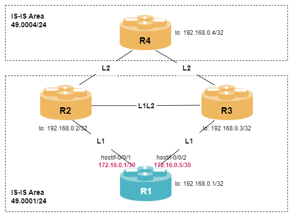
student@tour:~/trainings_resources/robot$ robot isis_single_area/isis_single_area_setup.robotIn order to get a better understanding, the lab setup is shown in the picture below.
IS-IS Overview
IS-IS, or Intermediate System to Intermediate System, is an open standard routing protocol. In IS-IS, a router is called an Intermediate System (IS). The original specification was published as ISO 10589 and describes a way to route datagrams as part of the OSI stack.
The protocol relies on device level addresses called network service access point (NSAP) addresses. Therefore, IS-IS does not use interface addresses. An interesting aspect is, that IS-IS runs at the link layer of the OSI model. The basic idea is that it does not make a lot of sense for a routing protocol to operate the control plane over the same network layer as the protocol it is doing the route calculation for, e.g., IPv4. IETF later defined the use of OSI IS-IS for IP routing in RFC 1195.
IS-IS is a link-state routing protocol which uses three fundamental different types of protocol data units (PDUs) to exchange information between routers:
-
Hello packets are used to establish and maintain IS-IS neighborship (or adjacencies)
-
Link State Packets (LSPs) are used to distribute routing information between IS-IS routers and populate the Link State Database (LSDB)
-
Sequence number packets (SNP) are used to synchronize the IS-IS LSDB and acknowledge the exchange of LSPs.
Based on the information stored in the LSDB, IS-IS calculates the best loop-free path to each destination with the Dijkstra Shortest Path First (SPF) algorithm.
IS-IS supports two levels of routing hierarchy known as Level-1 and Level-2, where Level-2 is considered to be the backbone of the network, while Level-1 forms areas to improve scalability. An IS-IS router can establish IS-IS adjacencies to another router either using Level-1 only, Level-2 only, or Level-1 and Level-2 at the same time.
Configuring IS-IS Neighborship
The IS-IS configuration is part of the routing protocol configuration within a routing instance, i.e., the corresponding CLI commands have the syntax set instance <instance> protocol isis <attribute> <value>.
There is a variety of parameters that can be set while configuring IS-IS, but let’s start with the most basic ones. In order to get IS-IS running, you must configure
-
area address
-
unique system ID
-
router ID
-
list of interfaces to run IS-IS on
-
authentication
The area address can be represented in 1, 3, 5, or 13 byte format and must include the area length in bits, e.g., using a 3-byte format, the area address looks like 49.0001/24. The first byte of the area address is called the authority format identifier (AFI) and you will often see it set to 49, which indicates private assignment. IS-IS routers must have identical area address in order to form Level-1 adjacencies.
The system ID is a 6-byte identifier which must be unique within the routing domain.
|
IS-IS does not rely on IP addresses, but usually has a IPv4 address on its loopback interface or as a system-id in a routing instance. Therefore, it is best practice to derive the system ID from the IPv4 loopback address using a schema called binary-coded decimal (BCD). 192.168.1.14 |
Configure IS-IS protocol in instance default with area 49.0001 and include the interfaces hostif-0/0/1/0, hostif-0/0/2/0 and lo-0/0/0/0 in the configuration. Choose your own system-id based on your loopback IPv4 address.
How many IS-IS adjacencies can you see and what’s the level?
Click to reveal the answer
cfg> set instance default protocol isis system-id 1921.6800.0001
cfg> set instance default protocol isis area 49.0001/24
cfg> set instance default protocol isis interface hostif-0/0/1/0
cfg> set instance default protocol isis interface hostif-0/0/2/0
cfg> set instance default protocol isis interface lo-0/0/0/0
cfg> set instance default protocol isis interface lo-0/0/0/0 passive true
cfg> commit
cfg> show isis neighbor
cfg> show isis interface
Instance: default
  Interface            Level   Adjacencies    Metric     Type                 Passive     LDP-sync
  lo-0/0/0/0               1             0    1000000    loopback                   1     -
  lo-0/0/0/0               2             0    1000000    loopback                   1     -
  hostif-0/0/1/0           1             0    1000000    point-to-point             0     -
  hostif-0/0/1/0           2             0    1000000    point-to-point             0     -
  hostif-0/0/2/0           1             0    1000000    point-to-point             0     -
  hostif-0/0/2/0           2             0    1000000    point-to-point             0     -
Although the configuration seems to be right, we do not see any IS-IS neighbors. Anything missing?
You should not see any adjacencies at all. But what’s the problem? Assuming everything is configured correctly, let’s check whether the remote switch is sending any useful packets or not.
op> capture interface hostif-0/0/1 direction in protocol isis file /home/supervisor/isis.cap start
Success : ifp file capture started

op> capture interface hostif-0/0/1 direction in protocol isis file /home/supervisor/isis.cap stop
Success : ifp file capture stopped

op> exit
supervisor@R1>tour:~ $ tcpdump -r isis.cap -v
reading from file isis.cap, link-type EN10MB (Ethernet)
12:05:00.135890 IS-IS, length 57
        p2p IIH, hlen: 20, v: 1, pdu-v: 1, sys-id-len: 6 (0), max-area: 3 (0)
          source-id: 1921.6800.0002, holding time: 30s, Flags: [Level 1, Level 2]
          circuit-id: 0x01, PDU length: 57
            Authentication TLV #10, length: 17                                   (1)
              HMAC-MD5 password: e916aa89f8f57edc112bf3edd0c8b758 (unchecked)    (2)
            Area address(es) TLV #1, length: 4
              Area address (length: 3): 49.0001
            Protocols supported TLV #129, length: 1
              NLPID(s): IPv4 (0xcc)
            IPv4 Interface address(es) TLV #132, length: 4
              IPv4 interface address: 172.16.0.2
            Point-to-point Adjacency State TLV #240, length: 1
Adjacency State: Initializing (1)| 1 | From the output we can see that the incoming IS-IS Hello packets are using the authentication TLV. |
| 2 | The type of authentication is MD5. |
Configuring IS-IS authentication is not mandatory but it is necessary that both sides agree on whether to authenticate or not. If authentication is used, the authentication type, key-id and key-string need to match.
Configure IS-IS authentication for Level-1 to be used with type md5 and plaintext password rtbrick. The key-id should be set to 1.
How many IS-IS adjacencies can you see and what’s the level?
Click to reveal the answer
cfg> set instance default protocol isis authentication level-1 type md5
cfg> set instance default protocol isis authentication level-1 key1-plain-text rtbrick
cfg> set instance default protocol isis authentication level-1 key-id1 1
cfg> commit
cfg> show isis neighbor
Instance: default
  Interface          System       Level   State   Type       Up since                Expires
  hostif-0/0/1/0     R2           L1      Up      P2P        Tue Jul 08 07:45:46     in 20s 280722us
  hostif-0/0/2/0     R3           L1      Up      P2P        Tue Jul 08 07:45:51     in 22s 293754us
You should see two neighboring routers with level L1L2, which indicates that there is a Level-1 and Level-2 adjacency at the same time.
Once the IS-IS adjacencies are up, we can inspect the IS-IS database for information learned from the neighbors. The IS-IS database must be the same on all routers within the same Level-1 area and on all routers in Level-2. A high-level summary of the database can be seen using the show isis database command:
cfg> show isis database
Instance: default, Level: 1
  LSP ID                    Sequence     Checksum     Lifetime     Overload     Attached
  1921.6800.0001.00-00           0x4       0xb033        65371            0            0
  R2.00-00                       0x2       0xf548        65365            0            0
  R3.00-00                       0x4       0xcf55        65370            0            0
Instance: default, Level: 2
  LSP ID                    Sequence     Checksum     Lifetime     Overload     Attached
  1921.6800.0001.00-00           0x7       0x5e0e        65372            0            0
From the output, we can see that there are three IS-IS routers in the Level-1 network. You may notice that the LSP-ID for all other IS-IS speakers is represented with a node name, while the local router is represented with its system-ID. This system-ID to hostname mapping is dynamically distributed in IS-IS and can be viewed using the show isis hostname command:
cfg> show isis hostname
Instance       System-ID           Hostname
default        1921.6800.0002      R2
default 1921.6800.0003 R3Configure IS-IS hostname to be system hostname.
Click to reveal the answer
cfg> set instance default protocol isis hostname R1
cfg> commit
cfg> show isis hostname
Instance       System-ID           Hostname
default        1921.6800.0001      R1
default        1921.6800.0002      R2
default        1921.6800.0003      R3
default        1921.6800.0004      R4
cfg>| Also not mandatory, it is always good to configure IS-IS hostname as well as it makes troubleshooting easier. |
Exploring IS-IS Database
In order to better understand IS-IS operation, let’s explore the IS-IS link-state database in more detail. IS-IS maintains a separate database for Level-1 and Level-2. The entries in the database represent the IS-IS Link State PDU (LSP) where the LSP ID takes the form
system-ID.XX-YY
where
-
the system-ID is given either as 6-octet hex number or resolved via the hostname database
-
XX is the N-selector which is usually 00 unless the node is a pseudonode
-
YY is the fragment number (starting with 00) in case the LSP was too long to fit into one PDU
For each router in the corresponding level, there should be one LSP with N-selector set to 00, for example
cfg> show isis database level-1
Instance: default, Level: 1
  LSP ID                    Sequence     Checksum     Lifetime     Overload     Attached
  R1.00-00                       0x5       0xdc12        65489            0            0
  R2.00-00                       0x2       0xf548        65146            0            0
  R3.00-00                       0x4       0xcf55        65151            0            0
The content of a specific LSP can be viewed using the show isis database command with either the lsp id <lsp-id> or system <hostname> option:
cfg> show isis database level-1 system R1
Instance: default, Level: 1
  LSP ID: R1.00-00
    Interface:
    LSP Header:
      Sequence: 0x5
      Checksum: 0xdc12
      Remaining lifetime: 65535 seconds
      Flags: Attached: 0, Overload: 0
    Packet:
      Length: 165 bytes
      Last received time: 2025-07-07T13:51:29.664927+0000
      Expiry: expires in 18h 10m 55s 347869us
    System ID: 1921.6800.0001                   (1)
    Dynamic Hostname TLV (137): R1
    Protocols Supported TLVs (129):
      Network layer protocol ID: IPv6
      Network layer protocol ID: IPv4
    Area Address TLVs (1):
      Area address: 49.0001                     (2)
    Authentication TLV (10):
      Type: md5
      Value: db897e4bffd0bc9197b664688fde97fd
    IS Reachability TLVs (22):                  (3)
      IS neighbor: 1921.6800.0002.00
      IS neighbor: 1921.6800.0003.00
    IPv4 Reachability TLVs (135):               (4)
      IPv4 prefix: 172.16.0.0/30                  Metric:  1000000   Internal   Up
      IPv4 prefix: 172.16.0.4/30                  Metric:  1000000   Internal   Up
      IPv4 prefix: 192.168.0.1/32                 Metric:  1000000   Internal   Up
    IPv6 Reachability TLVs (236):               (5)
      IPv6 prefix: fc00:c0a8:0:1::/64             Metric:  1000000   Internal   Up
      IPv6 prefix: fc00:c0a8:0:3::/64             Metric:  1000000   Internal   Up
      IPv6 prefix: fc00:c0a8::192:168:0:1/128     Metric:  1000000   Internal   Up
IS-IS uses Type Length Value (TLV) format to encode information. This mechanism is very flexible and allows enhancements to be implemented easily. If there is a new feature, then a new TLV has to be defined and added to the LSPs. By default, IS-IS supports both IPv4 (TLV 135) and IPv6 (TLV 236). The LSP contains the view of the network of corresponding node including
| 1 | its system ID |
| 2 | the area address |
| 3 | a list of directly connected IS-IS neighbors |
| 4 | a list of directly connected IPv4 networks |
| 5 | a list of directly connected IPv6 networks |
So far, we have only seen LSP IDs with N-selector set to 00. The concept of a pseudonode arises primarily in broadcast environments, where you have multiple routers connected to the same broadcast medium like Ethernet. By default, IS-IS interfaces in RBFS are of type point-to-point. Let’s add another interface with type broadcast to create a pseudonode.
Configure an additional interface hostif-0/0/11/0 in the existing IS-IS area 49.0001. Set the interface type to broadcast.
Click to reveal the answer
cfg> set instance default protocol isis interface hostif-0/0/11/0 type broadcast
cfg> commit
cfg> show isis neighbor
Instance: default
  Interface          System       Level   State   Type       Up since               Expires
  hostif-0/0/1/0     R2           L1      Up      P2P        Tue Jul 08 13:45:46    in 29s 413888us
  hostif-0/0/2/0     R3           L1      Up      P2P        Tue Jul 08 13:45:51    in 25s 407533us
  hostif-0/0/11/0    R5           L1      Up      Broadcast  Tue Jul 08 13:53:04    in 29s 413704us
After the new adjacency has come up, we observe that we now have two additional entries in the link-state database instead of just one new entry:
cfg> show isis database level-1
Instance: default, Level: 1
  LSP ID                    Sequence     Checksum     Lifetime     Overload     Attached
  R1.00-00                       0x3       0x9964        64096            0            0
  R2.00-00                       0x3       0x98aa        64096            0            0
  R3.00-00                       0x3       0x231a        64096            0            0
  R4.00-00                       0x2       0xed91        64096            0            0
  R5.00-00                       0x2       0x7802        64096            0            0
  R5.01-00                       0x1       0xfac6        64096            0            0
The entry R1.01 refers to a pseudonode that represents the designated intermediate system (DIS). The DIS is a router elected from all routers on a broadcast network. Once elected, the DIS creates a pseudonode to simplify the network topology. This reduces the number of routers each router must track in its link-state database. As a result, each router on the broadcast network only forms an IS-IS adjacency with the pseudonode, which is responsible for generating and distributing the link-state information for the network. Note that, unlike OSPF, there is no backup DIS.
We can verify from the output below, that router R5 only forms and IS-IS adjacency with the pseudonode 1921.6800.0005.01, but not with router.
cfg> show isis database level-1 node R5.00
Instance: default, Level: 1
  LSP ID: R5.00-00
  <...>
    IS Reachability TLVs (22):
      IS neighbor: 1921.6800.0005.01              Metric:      100
    IPv4 Reachability TLVs (135):
      IPv4 prefix: 172.16.0.20/30                 Metric:      100   Internal   Up
      IPv4 prefix: 192.168.0.5/32                 Metric:  1000000   Internal   Up
  <...>

cfg> show isis database level-1 node R5.01
Instance: default, Level: 1
  LSP ID: R5.01-00
  <...>
    IS Reachability TLVs (22):
      IS neighbor: 1921.6800.0001.00              Metric:        0
      IS neighbor: 1921.6800.0005.00              Metric:        0
On the other hand, the database entry for R5.01 reveals, that the pseudonode has two adjacent neighbors, R1 and R5.
Based on the link-state database, IS-IS uses the SPF algorithm to calculate the best path to each destination. The best path is the one with the lowest total metric to the destination. As IS-IS is independent of IP addresses, the result of the SPF calculation reflects a topology based on system IDs:
cfg> show isis spf result level-1
Instance: default, Level: 1
  Destination Node          Metric       Neighbor Node         Interface         Nexthop   Address
  1921.6800.0001.00                0                           local
  1921.6800.0002.00          1000000     1921.6800.0002.00     hostif-0/0/1/0    IPv4      172.16.0.2
1921.6800.0003.00 1000000 1921.6800.0003.00 hostif-0/0/2/0 IPv4 172.16.0.6In the previous section, we have seen that be default IS-IS exchanges reachability information for both IPv4 and IPv6. Most often in backbone networks IPv4 reachability is sufficient. Disable IPv6 support with the ipv6-disable knob in the ISIS configuration and verify the result.
Click to reveal the answer
cfg> set instance default protocol isis ipv6-disable true
cfg> commit
cfg> show isis database level-1 system R1
Instance: default, Level: 1
  LSP ID: R1.00-00
    Interface:
    LSP Header:
      Sequence: 0x3
      Checksum: 0x9964
      Remaining lifetime: 65535 seconds
      Flags: Attached: 0, Overload: 0
    Packet:
      Length: 132 bytes
      Last received time: 2025-07-08T07:51:52.900250+0000
      Expiry: expires in 17h 6m 44s 950790us
    System ID: 1921.6800.0001
    Dynamic Hostname TLV (137): R1
    Protocols Supported TLVs (129):
      Network layer protocol ID: IPv4
    Area Address TLVs (1):
      Area address: 49.0001
    Authentication TLV (10):
      Type: md5
      Value: 65165aa93da9a18905352f2493b5806b
    IS Reachability TLVs (22):
      IS neighbor: 1921.6800.0002.00              Metric:  1000000
      IS neighbor: 1921.6800.0003.00              Metric:  1000000
      IS neighbor: 1921.6800.0005.01              Metric:  1000000
    IPv4 Reachability TLVs (135):
      IPv4 prefix: 172.16.0.0/30                  Metric:  1000000   Internal   Up
      IPv4 prefix: 172.16.0.4/30                  Metric:  1000000   Internal   Up
      IPv4 prefix: 172.16.0.20/30                 Metric:  1000000   Internal   Up
      IPv4 prefix: 192.168.0.1/32                 Metric:  1000000   Internal   Up
Note, there are no IPv6 Reachability TLV entries anymore.
Configuring Level-1 Routing
Now that we have IS-IS protocol up and running, let’s get back to the two-level network hierarchy that IS-IS provides. A network can be split into IS-IS areas. All routers within a single area are called Level-1 (L1) router. All routers in the backbone area are called Level-2 (L2) routers. For L1 routers to reach destinations outside of its area, there has to be at least one L1L2 router, i.e., a router within the L1 area that also connects to the L2 backbone.
|
All routers within the same level share the same link state database (LSDB). IS-IS networks are segmented into areas in order to reduce flooding of LSPs and reduce the size of the LSDB. Therefore, configuring IS-IS enhances the scalability of your network. |
In RBFS, there is no global command to enable or disable the IS-IS level. Association to a level is configured on a per-interface bases.
You have three interfaces configured within the IS-IS routing protocol. Disable level-2 adjacencies for each of these interfaces. How do the IS-IS neighbors and IS-IS interfaces change?
Click to reveal the answer
cfg> set instance default protocol isis interface hostif-0/0/1/0 level-2 adjacency-disable true
cfg> set instance default protocol isis interface hostif-0/0/2/0 level-2 adjacency-disable true
cfg> set instance default protocol isis interface hostif-0/0/11/0 level-2 adjacency-disable true
cfg> set instance default protocol isis interface lo-0/0/0/0 level-2 adjacency-disable true
cfg> commit
cfg> show isis neighbor
Instance: default
  Interface          System             Level   State   Type       Up since                Expires
  hostif-0/0/1/0     R2                 L1      Up      P2P        Tue Jul 08 08:29:15     in 29s 543410us
  hostif-0/0/2/0     R3                 L1      Up      P2P        Tue Jul 08 08:29:15     in 20s 465558us
  hostif-0/0/11/0    R5                 L1      Up      Broadcast  Tue Jul 08 08:51:52     in 22s 66253us
cfg> show isis interface
Instance: default
  Interface            Level   Adjacencies    Metric     Type                 Passive     LDP-sync
  lo-0/0/0/0               1             0    1000000    loopback                   1     -
  hostif-0/0/1/0           1             1    1000000    point-to-point             0     -
  hostif-0/0/2/0           1             1    1000000    point-to-point             0     -
  hostif-0/0/11/0          1             1    1000000    broadcast                  0     -
In the show isis neighbor command, the level has changed from L1L2 to L1.
We remember that the loopback IPv4 address of router R4 is 192.168.0.4/32. Let’s take a look at the routing table for this destination:
cfg> show route prefix 192.168.0.4/32
Instance: default, AFI: ipv4, SAFI: unicast
Prefix/Label           Source            Pref    Next Hop         Interface
0.0.0.0/0              isis              15      172.16.0.6       hostif-0/0/2/0
                                                 172.16.0.2       hostif-0/0/1/0
As R1 is now a Level-1 only router, it does not get any routing information from outside the area. But reachability is still available through the default route via R2 and R3. However, if we inspect the LSP of R2 again, we won’t find any reachability TLV for 0.0.0.0/0:
cfg> show isis database level-1 system R2
Instance: default, Level: 1
  LSP ID: R2.00-00
    Interface:
    LSP Header:
      Sequence: 0x11
      Checksum: 0x9ff
      Remaining lifetime: 65534 seconds
      Flags: Attached: 1, Overload: 0
    <...>
    IPv4 Reachability TLVs (135):
      IPv4 prefix: 172.16.0.0/30                  Metric:      100   Internal   Up
      IPv4 prefix: 172.16.0.12/30                 Metric:      100   Internal   Up
      IPv4 prefix: 192.168.0.2/32                 Metric:  1000000   Internal   Up
    <...>
In IS-IS, a L1L2 router that has an adjacency to a L2 router outside of its own area, informs all L1 router that it is a possible exit point by setting the Attached bit in the LSP header. For a L1 router, it is possible to skip evaluation of attached bit and thus not install any default router. The corresponding command is
cfg> set instance default protocol isis ignore-attached-bit true
cfg> commit