RBFS C-BNG with Redundancy for IPoE Subscribers
Overview
RtBrick provides reference design architectures which have been designed and validated with the in-house testing tools and methods. This document guides you to validate RBFS Consolidated BNG - IPoE with Redundancy implementation.
About RBFS Redundancy
RBFS Redundancy protects subscriber services from node and link outages. It provides mechanisms to enhance network resiliency that enables subscriber workloads to remain functional by ensuring a reliable switchover in the event of a node or link outage. With RBFS Redundancy, if one node goes down, another node can automatically take over the services for a subscriber group.
RBFS Redundancy provides protection to subscriber groups using an active standby node cluster model. RBFS Redundancy architecture consists of active-standby node cluster and one node is active for a subscriber group that runs workloads at a time. The peer node, which is identical to the first node, mirrors the concurrent subscriber state data from the peer, takes over workloads in the event of a node or link failure. It ensures that traffic can keep flowing in the event of an outage. For more information about RBFS redundancy solution, see RBFS Redundancy Solution Guide.
About this Guide
You must read this document in conjunction with the RBFS C-BNG for IPoE Subscribers Reference Design Guide that provides all required configuration information and quick steps for validating the RBFS C-BNG with IPoE implementation. This document provides information about the RBFS C-BNG - IPoE deployment in Redundancy (high availability) mode. It is mandatory to complete all the required configurations described in the RBFS C-BNG for IPoE Subscribers Reference Design Guide before deploying the C-BNG in the redundancy mode.
The document presents a single use case scenario and provides information specifically on how to validate this particular implementation and for more information on any specific application, refer to https://documents.rtbrick.com/.
Currently, the scope of the guide is limited to the basic features and configurations for validation purpose. This guide does not provide information about the advanced RBFS features such as multicast.
RBFS CBNG- IPoE with Redundancy Implementation Architecture
RBFS C-BNG – IPoE with redundancy architectural diagram shows two bare metal switches, installed with the RBFS C-BNG software. The devices are deployed in active and standby mode. The device cbng1 is configured as active device and cbng2 as a standby device. If one node goes down, the other node becomes stand-alone and takes over the subscribers for a subscriber group. The RBFS devices are connected to core routers and also connected to servers: NTP, RADIUS, and TACACS+.
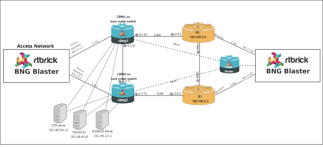
When the active device goes down or a link failure between the active RBFS device and OLT device, the standby RBFS device detects the same and takes over from the previously active device.
The RBFS devices are directly connected to the BNG Blaster which is a home-grown open-source network testing platform for simulating thousands of IPoE subscribers. The diagram shows the simulated IPoE subscriber traffic between the RBFS device and the core network.