RBFS C-BNG with Redundancy for IPoE Subscribers
Overview
RtBrick provides reference design architectures designed and validated with in-house testing tools and methods. This document guides you to validate RBFS Consolidated BNG - IPoE with Redundancy implementation.
About RBFS Redundancy
RBFS Redundancy protects subscriber services from node and link outages. It provides mechanisms to enhance network resiliency that enables subscriber workloads to remain functional by ensuring a reliable switchover in the event of a node or link outage. With RBFS Redundancy, if one node/protected link goes down, another node can automatically take over the services for a subscriber group.
RBFS Redundancy protects subscriber groups using an active-standby node cluster model. The active node for a subscriber group runs the workload, and the peer node, which acts as standby, mirrors the subscriber state data from the peer (active) and takes over the workload in the event of a node or link failure. It ensures that traffic can keep flowing in the event of an outage. For more information about RBFS redundancy solution, see RBFS Redundancy Solution Guide.
About this Guide
It is recommended that you read this document after reading the RBFS C-BNG for IPoE Subscribers Reference Design Guide, which provides all required configuration information and quick steps for validating the RBFS C-BNG with IPoE implementation. The configurations related to the protocols, Quality of Service (QoS), subscriber management, and FreeRADIUS Server are part of the RBFS C-BNG for IPoE Subscribers Reference Design Guide.
This document provides information about the RBFS C-BNG - IPoE deployment in Redundancy (high availability) mode. It is mandatory to complete all the required configurations described in the RBFS C-BNG for IPoE Subscribers Reference Design Guide before deploying the C-BNG in the redundancy mode.
The document presents a single use case scenario and provides information on validating this implementation. For more information on any specific application, refer to https://documents.rtbrick.com/.
Currently, the guide’s scope is limited to the basic features and configurations for validation purposes. This guide does not provide information about the advanced RBFS features such as multicast.
RBFS CBNG- IPoE with Redundancy Implementation Architecture
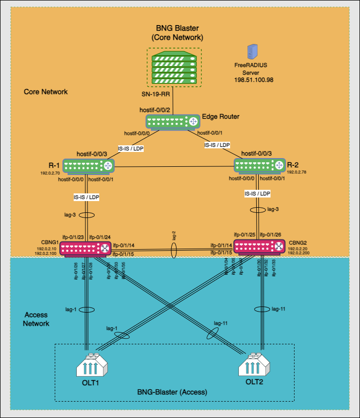
The architectural redundancy diagram below for RBFS C-BNG IPoE shows two bare metal switches installed with RBFS C-BNG software. This topology aims to demonstrate complete IPoE subscriber emulation with redundancy and routing to connect to the network uplink.
The devices are deployed in active and standby mode with respect to the lag bundles. cbng1 is configured as the active device for lag-1, and cbng2 is the standby device for lag-1. If one node goes down, the other node becomes stand-alone and takes over the subscribers for a subscriber group. RBFS devices (CBNGs) are connected to core routers on one side and OLTs (simulated by BNGBlaster) on the other.
When the active device goes down or a link failure occurs between the active RBFS device and the OLT device, the standby RBFS device detects the same and takes over from the previously active device.
In this topology:
-
SN-19-RR is the Service Node which is a Linux container running on an Ubuntu server. BNG Blaster, which emulates routing and access functions, runs on this container. This container also runs FreeRADIUS, which emulates RADIUS functions.
-
There are three routers; two acting as core routers (R-1 & R-2) and the third one as the Edge router. R-1, R-2, and Edge Router are RBFS virtual helper modes. The devices need not be RtBrick C-BNGs.
-
CBNG1 and CBNG2 are the DUTs, which are two bare metal switches installed with the RBFS C-BNG software. On one side, these are connected to the Access Network, while on the other side, they are connected to the Core Network.
-
The CBNGs form IS-IS adjacency and LDP session with the core routers R1 and R2, and the route reflectors (2 of them advertising 1M IPv4 prefixes each and the other two advertising 250K IPv6 prefixes each) are simulated by the BNG-Blaster.
-
The topology brings up 20K IPoE subscribers (2 OLTs with 10K subscribers each simulated by BNG Blaster) over a LAG interface. A failure of a CBNG does not affect a subscriber’s services since they are backed up among the CBNGs.