1. RBFS Redundancy for Subscriber Groups
1.1. Overview
Node outages and link failures that may occur on an access network can bring down the subscriber services. These network outages affect critical workloads and continuity of business. So, it is essential to set up a network that is resilient and responds quickly to the events and protect the network from outages.
The following diagram represents a simple access network without redundancy.
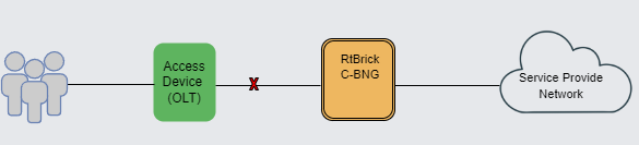
RBFS Redundancy protects subscriber services from node or link outages. It provides mechanisms to enhance network resiliency that enables subscriber workloads to remain functional by ensuring a reliable switchover in the event of a node or link outage. With RBFS Redundancy, if one node goes down due to node or link failure, another node can automatically take over the services.
|
|
Currently, RBFS Redundancy supports only IPoE. |
1.2. Understanding RBFS Redundancy
RBFS Redundancy provides protection to subscriber groups using an active-standby node cluster model. In the active-standby node cluster, the active node (for a subscriber group) performs subscriber services. The standby device mirrors concurrent subscriber state data from the active peer (for that redundancy session). Both the nodes, paired for redundancy, keep sending 'keepalive' messages to each other to check the health status. RBFS Redundancy is centered around subscriber groups, known as redundancy sessions.
|
|
The document uses the term C-BNG throughout the document. C-BNG stands for consolidated BNG. A C-BNG is a BNG that contains all the BNG functionalities together in a single platform. Unlike the spine-leaf topology, where the functionalities are distributed to spine platforms and leaf platforms separately based on their roles, C-BNG platform includes all functionalities together in a single platform. |
|
|
RBFS Redundancy is not supported on spine-leaf network topology as the RBFS spine-leaf topological architecture itself innately provides a redundant and resilient network. |
1.2.1. Inter-BNG Link
C-BNG platforms, paired for redundancy, are connected with an RD TCP link. This RD TCP connection can be formed either directly or through the core network. It uses IS-IS (for unicast reachability) and LDP (for labeled unicast reachability) between the active and standby nodes. The link between the C-BNG pairs establishes connectivity and the link is used to send 'keepalive' messages and data mirroring for subscriber state synchronization.
When the link between the C-BNGs goes down, the redundancy session comes to a halt and C-BNGs move to standalone mode. If the link goes down, the Keepalive messages cannot be exchanged between the C-BNGs and the CBNGs move to the standalone state only after the hold-timer gets expired and the previously synchronized subscriber session data becomes invalid.
1.2.2. Redundancy Session
Redundancy session is a binding mechanism that is used to pair C-BNGs for redundancy. RBFS Redundancy allows grouping of subscribers, under a redundancy session and each redundancy session is represented by a redundancy session ID. Simply, an RBFS Redundancy session represents a redundancy group of subscribers. A redundancy session enables linking the LAG with that particular redundancy session (subscriber group). When you define a value for the redundancy session ID, this ID should be unique and the same for both redundancy pairs. When two nodes get the same session ID, they recognize each other as the peer nodes for a particular redundancy session (subscriber group). The TCP session establishment between the nodes occurs after the pairing with the redundancy session ID. Once the TCP session is established, the nodes use this channel for subscriber data mirroring and synchronization and for health status monitoring.
A C-BNG chassis can contain multiple redundancy sessions. Multiple C-BNG nodes can be active nodes for one or more subscriber groups (redundancy sessions) that serve the subscribers and they can, at the same time, be standby nodes for other subscriber groups.
One node, which is paired for redundancy, can perform subscriber services for more than one redundancy session (subscriber group). The peer node, which is identical to the first node, contains the same subscriber group (redundancy session) as a standby. And in the event of the first node goes down due to any outage, the standby node can take over subscriber service for this redundancy session.
RBFS Redundancy allows running a redundancy session actively on one node and back up the same redundancy session (subscriber group) on a different (standby) C-BNG node. In RBFS redundancy, in fact, there is no active node or standby node. It is active subscriber group and standby subscriber group. A C-BNG node can be active for a subscriber group and at the same time it can be a standby for a different subscriber group. You can park a maximum number of 64 redundancy sessions (either active or standby) on a C-BNG node.
1.2.3. RBFS Redundancy Architecture
The following architectural diagram provides a high-level view of RBFS in redundancy mode. It shows two RBFS nodes, paired for redundancy, deployed in a active-standby node cluster, with their interfaces are connected with an RD TCP connection. These peer nodes use the RD TCP connection for sending 'keepalive' messages and data mirroring for subscriber state synchronization.
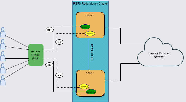
Both of the nodes are connected to an access device (OLT device in this scenario) on one end from where it receives subscriber traffic and sends traffic. The nodes are also connected to the core network on the other end.
If connectivity from BNG to the core network goes down,
The node 'C-BNG 1' is in active state and performs subscriber services for the 'Session 1' (redundancy subscriber group). 'Session 1' is also mirrored in the C-BNG 2 in standby mode. The standby device mirrors concurrent subscriber state data for 'Session 1' from the active peer. If an active node goes down due to any reason, the peer node detects the outage and uses mirrored 'Session 1' to perform subscriber services.
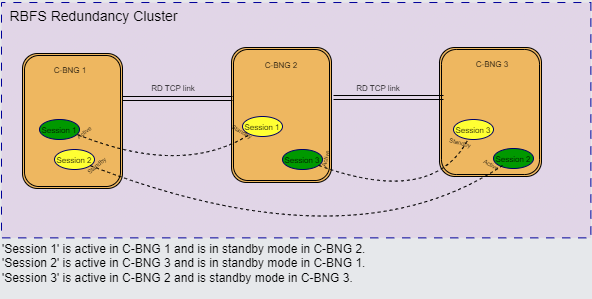
One C-BNG node acts as active node for one or more sessions (subscriber redundancy groups) and as a standby C-BNG for other subscriber redundancy groups at the same time. The following diagram illustrates the scenario.
RBFS Redundancy can mitigate the following types of failures:
-
Link failure Between Active RBFS Node and Access Node (OLT, DSLAM or MSAN)
-
Node Outage
1.2.3.1. Redundancy for Node Outage
A node outage, which can bring down the subscriber services, can occur due to many reasons on a network. RBFS Redundancy helps to minimize the impact and reduce interruptions and downtime by providing a resilient system. In the event of a node outage, RBFS Redundancy triggers switchover in which the standby node takes over from the active node with very minimal impact on the subscriber services.
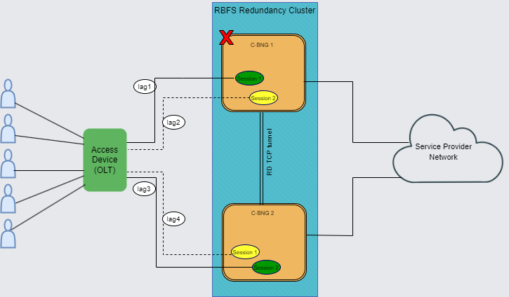
The diagram shows cbng1 as an active node serving subscribers and cbng2 stays as a standby. When an active node goes down, the standby node detects the same and takes over from the active RBFS node. In a node outage scenario, the node becomes unresponsive and cannot maintain communication with its peer node the RD TCP link.
1.2.3.2. Redundancy for Link Failure
In RBFS Redundancy, Link Aggregation combines multiple physical links into a single logical link. If a member link, which is part of a LAG, goes down, the LAG fails. The diagram shows the 'cbng1' and 'cbng2' deployed in redundancy mode and is connected to the access device with LAGs. When the LAG between 'cbng1' and the access node goes down, the 'cbng1', which is running 'Session 1', becomes inactive for the subscriber group. So the 'cbng2', which is the standby for 'Session 1', detects the failure of 'cbng1' and starts performing subscriber services for 'Session 1' by providing a quick recovery from the disruption.
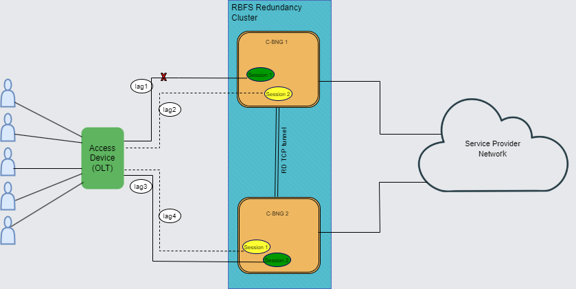
In this link or LAG failure scenario, cbng1 is in a healthy state, only the LAG interface went down. It cannot perform subscribe services for the particular redundancy session. However, it can keep communication with its peer node as the RD TCP channel.
1.2.4. Subscriber Data Synchronization
RBFS Redundancy subscriber data from the active node is always synced to the standby node. So that if the active node goes down, the standby node takes over and restores traffic forwarding which was previously performed by its peer node. It ensures that traffic can keep flowing even in the event of an outage.
1.2.5. Node States in Redundancy
In RBFS redundancy, C-BNG nodes have different states for various redundancy sessions. Typically, RBFS redundancy nodes encounter the following states for redundancy sessions:
Active: All subscribers are served by active node in the RBFS active-standby node cluster. One node which is active for a redundancy session can be a standby node for a different session. Nodes, that are paired for redundancy, send 'keepalive' messages to each other and also synchronize all subscriber state data with the peer node. The priority values that you specify for the redundancy nodes determine the roles of active and standby. The node that receives the higher priority value for the session ID assumes the role of active for that subscriber group. To set one device as 'active', you must specify higher priority value for the redundancy session for that node.
Standby: Standby node is identical with the active node and synchronizes subscriber data concurrently from peer node. It keeps communication with the peer node to monitor node health status using 'keepalive' messages. The node that gets the lower priority value for the redundancy session ID assumes the role of standby. Standby node for a subscriber group does not perform any subscriber services for that group unless or until the active node encounters an outage.
Down: When a node becomes inactive due to an outage, it is considered as 'down'. In the event of a node outage, it is completely down and cannot perform subscriber services and any communication with its peer node. But in the case of a LAG (between the node and access node) failure, the node cannot perform subscriber services, but it can communicate with the peer node through the RD TCP connection. So that the subscriber state synchronization occurs without any interruption.
Stand Alone: When the active node goes down, the switchover occurs and standby takes over the subscriber service. In this scenario, the serving node is in 'stand alone' state (for that redundancy session) as it has no peer node for redundancy.
1.2.6. Revert or Rollback
In RBFS Redundancy, after a node or link failure and the subsequent switchover, the standby takes over and continues the subscriber service for that subscriber group even after the other node (previously active) recovers from the failure. There is no automated rollback or revert to the previously active router. However, administrators can perform a manual switchover.
1.2.7. Monitoring Node Health Status
The RBFS nodes, which have switchover capacities, monitor each other for the health status. RBFS Redundancy uses 'keepalive' messages that check on the health of the RBFS nodes. Both of the devices send 'keepalive' messages to each other in every five seconds. One Node can detect a failure if it does not receive 'keepalive' messages for a period of 20 seconds from the other node.
1.2.8. Redundancy Clients
There are multiple RBFS daemons that participate for providing redundancy. They include redundancy daemon, (rd), LAG daemon (lagd), interface daemon (ifmd), subscriber daemon (subscriberd), IPoE daemon (ipoed). These daemons, which perform various roles, are known as redundancy clients.
1.2.8.1. Redundancy Daemon
Redundancy Daemon is responsible for establishing high availability connections. It monitors the ecosystem and detects any outage that may happen on the network. It performs assigning the roles of active or standby to the nodes depending on the priority configured on the node. The daemon triggers a switchover to the standby node if a failure occurs. It responds to the failure events which are reported locally by daemons who are the redundancy clients. It also cleanses the data after switchover from the node that went down.
1.3. Supported Hardware Platforms
Currently, RBFS can be deployed in redundancy mode using the RBFS C-BNG (Consolidated BNG) switches. RBFS C-BNG software provides complete BNG functionalities on a single compact hardware switch. You can use the following hardware platforms to deploy RBFS in redundancy mode.
-
UfiSpace S9600-72XC: The UfiSpace S9600-72XC is a multi-function, disaggregated white box aggregation routing platform that is equipped with Broadcom’s Qumran2c chipset. It features 64x25GE and 8x100GE high speed ports with a switching capacity of up to 2.4Tbs.
-
Edgecore AGR420: AGR420 is a high performance 25GbE aggregation router that consists of fixed 64 x 10G/25G SFP28, 8 x 100GE QSFP28 and 2 x 100G QSFP-DD network interface configurations.
1.4. RBFS Redundancy Requirements
The following are the requirements which must be met for setting up RBFS Redundancy.
-
Ensure that both of the platform devices, on which RBFS software run, must be the same model.
-
Ensure that the devices should run the same version of RBFS software. RBFS software 23.2.1 and later versions support deployment in redundancy mode.
-
NTP must be configured on both the devices for matching the timestamps.
2. Deploy RBFS in Redundancy Mode
2.1. RBFS Redundancy
This section provides information on how to deploy RBFS C-BNG device pair to achieve redundancy. The following workflow diagram depicts the end-to-end deployment of RBFS in Redundancy mode:
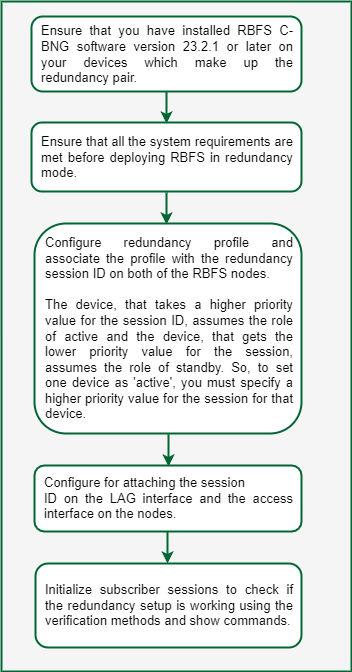
You must perform the following tasks to deploy the RBFS devices in redundancy mode. These configurations must be performed on both of the devices.
-
Configure Redundancy Profile
-
Configure Session for Redundancy
-
Configure Link Aggregation Group for Redundancy
-
Configure Access for Redundancy
2.1.1. Configuration Syntax and Commands
The following sections describe syntax and commands for various configurations.
2.1.1.1. Configuring Redundancy Profile
Redundancy profile configuration is used to provide peer identity in redundancy. While configuring the redundancy profile on the nodes, you must specify IP addresses of both the peer nodes. Based on the priority value that you specify for the session ID, the peers take the roles of active and standby for the Session.
Syntax:
set redundancy profile <name>
| Attribute | Description |
|---|---|
peer |
Redundancy configuration |
switchover-hold-timer |
Minimum time interval between consecutive switch-overs in seconds. |
Run the following commands to configure redundancy profile.
set redundancy profile rd_ipoe
set redundancy profile rd_ipoe peer ipv4 remote-address 198.51.100.2
set redundancy profile rd_ipoe peer ipv4 update-source 198.51.100.1
set redundancy profile rd_ipoe peer ipv4 instance default
Example Configuration:
supervisor@rtbrick>cbng1.rtbrick.net: cfg> show config redundancy profile
{
    "rtbrick-config:profile": [
      {
        "name": "rd_ipoe",
        "peer": {
          "ipv4": {
            "remote-address": "198.51.100.2",
            "update-source": "198.51.100.1",
            "instance": "default"
          }
        }
      }
    ]
  }
2.1.1.2. Configuring Session for Redundancy
You can configure Redundancy Session with a unique session ID. You can define the system priority value (which determines active and standby roles) and the associate Redundancy profile configuration in the Redundancy Session configuration.
Syntax:
set redundancy session <session-id>
| Attribute | Description |
|---|---|
keepalive-interval |
Keepalive message transmission interval in seconds. Default is 5 seconds. |
priority |
Session priority |
profile |
Profile name |
Run the following commands to configure session for redundancy.
set redundancy session 100
set redundancy session 100 priority 10
set redundancy session 100 profile rd_ipoe
Configuration Example:
supervisor@rtbrick>cbng2.rtbrick.net: cfg> show config redundancy session
{
    "rtbrick-config:session": [
      {
        "session-id": 100,
        "priority": 10,
        "profile": "rd_ipoe"
      }
    ]
  }
2.1.1.3. Configuring LAG for Redundancy
You must associate the Redundancy Session with the LAG. While configuring LAG for redundancy, you must specify the session ID to associate the LAG with the Redundancy Session. LAG can identify its Redundancy Session with this mapping.
Syntax:
set link-aggregation interface <interface-name> options
| Attribute | Description |
|---|---|
description |
Link aggregation interface description. |
member-interface |
Link aggregation member interface configuration |
minimum-link-count |
Minimum number of active member links required for the link aggregation interface. default values is 1. |
mode |
Mode of the link aggregation interface, static or lacp. default mode is lacp. |
rd-role |
Role of the link aggregation interface, active or standby. |
rd-system-priority |
The value for the system priority range from 1 to 65535. The lower the value, the higher the system priority. default value is 65535. |
redundancy-session-id |
The value for the redundancy group session id range from 1 to 65535. |
system-id |
Redundancy System ID of link-aggregation interface. |
Run the following commands to configure LAG for redundancy.
set link-aggregation interface lag-1
set link-aggregation interface lag-1 mode lacp
set link-aggregation interface lag-1 minimum-link-count 1
set link-aggregation interface lag-1 redundancy-session-id 100
set link-aggregation interface lag-1 system-id a8:b5:7e:8f:66:43
set link-aggregation interface lag-1 member-interface ifp-0/1/260
Example Configuration:
supervisor@rtbrick>cbng2.rtbrick.net:: cfg> show config link-aggregation interface lag-1
{
    "rtbrick-config:interface": [
      {
        "interface-name": "lag-1",
        "mode": "lacp",
        "minimum-link-count": 1,
        "redundancy-session-id": 100,
        "system-id": "11:22:33:44:55:66",
        "member-interface": [
          {
            "member-interface-name": "ifp-0/0/4"
          }
        ]
      }
    ]
  }
2.1.1.4. Configuring Access for Redundancy
IPoE and Redundancy Session mapping is essential to associate the Redundancy Session with IPoE. While configuring access for redundancy, you must specify access type as IPoE.
Syntax:
set access interface double-tagged <name> <options>
| Attribute | Description |
|---|---|
aaa-profile-name |
AAA profile name |
access-profile-name |
Access profile name |
access-type |
Access service type |
gateway-ifl |
IPoE gateway IFL (unnumbered source IFL) |
max-subscribers-per-mac |
Restrict maximum subscribers per MAC address |
max-subscribers-per-vlan |
Restrict maximum subscribers per VLAN |
redundancy-session-id |
Redundancy session id for this interface |
service-profile-name |
Service profile name |
vlan-profile-enable |
Enable VLAN profiles |
Run the following commands access for redundancy.
set access interface double-tagged lag-1 1001 1100 1001 1100
set access interface double-tagged lag-1 1001 1100 1001 1100 access-type IPoE
set access interface double-tagged lag-1 1001 1100 1001 1100 access-profile-name ipoe
set access interface double-tagged lag-1 1001 1100 1001 1100 aaa-profile-name ipoe-aaa
set access interface double-tagged lag-1 1001 1100 1001 1100 gateway-ifl lo-0/0/0/10
set access interface double-tagged lag-1 1001 1100 1001 1100 redundancy-session-id 100
Example Configuration:
supervisor@rtbrick>cbng1.rtbrick.net: cfg> show config access interface double-tagged lag-1
{
    "rtbrick-config:double-tagged": [
      {
        "interface-name": "lag-1",
        "outer-vlan-min": 1001,
        "outer-vlan-max": 1100,
        "inner-vlan-min": 1001,
        "inner-vlan-max": 1100,
        "access-type": "IPoE",
        "access-profile-name": "ipoe",
        "aaa-profile-name": "ipoe-aaa",
        "gateway-ifl": "lo-0/0/0/10",
        "redundancy-session-id": 100
      }
    ]
  }
2.1.2. Switchover Manually
Administrators can perform a manual switchover from an active node to a standby node. Use the following command to perform switchover:
switch-over session <session-id> confirm
3. RBFS Redundancy Operational Commands
3.1. Redundancy Show Commands
With the RBFS Command Line Interface, you can view output of operational commands. The redundancy operational commands provide detailed information about the RBFS redundancy operations.
3.1.1. Client Statistics
Syntax:
show redundancy client <name> statistics
This command displays information from redundancy client (daemon) which is a participant in the redundancy sessions. The daemons ifmd, ipoed.1, lagd, and subscriberd.1 are the client daemons in redundancy sessions.
Command:
show redundancy client lagd statistics
Example:
supervisor@rtbrick>ufi08.q2c.u23.r4.nbg.rtbrick.net: op> show redundancy client lagd statistics
Session id: 100, Profile: rd_ipoe
  Agent State: down
  TCP operational state: down
  Message statistics:
    Keep alive sent: 0
    Keep alive received: 0
  Last 5 state changes: [Latest first]
    down                : 2022-12-08T08:47:06.077823+0000
    demote-ready        : 2022-12-08T08:47:06.077798+0000
    demote-infra-wait   : 2022-12-08T08:47:06.077769+0000
    demote-app-wait     : 2022-12-08T08:47:06.077713+0000
    active              : 2022-12-08T06:57:53.058172+0000
  Connection statistics:
    Peer Address: 198.51.100.2
    Application down notifications: 0
    Connection down notifications: 0
    Retry count: 0
    Session down received: 8
3.1.2. Session Details
Syntax:
show redundancy session detail
The command displays RD session details.
Command:
show redundancy session detail
Example:
supervisor@rtbrick>ufi08.q2c.u23.r4.nbg.rtbrick.net: op> show redundancy session detail
Redundancy session ID: 100, Update source: 198.51.100.1, Peer: 198.51.100.2.
  Instance: default, Profile name: rd_ipoe, Local priority: 20
  State: down, Previous state: active, Last state transition time: 2022-12-08T08:47:06.071930+0000
  TCP operational state: down
  Message statistics:
    Keep alive sent: 21516
    Keep alive received: 21515
    Switch overs detected: 0
  Timers:
    Connect retry interval: 2000
    keep alive timer interval: 3000
    Holddown timer interval: 9000
3.1.3. Session ID Details
Syntax:
show redundancy session <ID> detail
The command displays RD session detail for a session ID. Command:
show redundancy session 100 detail
Example:
supervisor@rtbrick>ufi08.q2c.u23.r4.nbg.rtbrick.net: op> show redundancy session 100 detail
Redundancy session ID: 100, Update source: 198.51.100.1, Peer: 198.51.100.2
  Instance: default, Profile name: rd_ipoe, Local priority: 20
  State: down, Previous state: active, Last state transition time: 2022-12-08T08:47:06.071930+0000
  TCP operational state: down
  Message statistics:
    Keep alive sent: 21516
    Keep alive received: 21515
    Switch overs detected: 0
  Timers:
    Connect retry interval: 2000
    keep alive timer interval: 3000
    Holddown timer interval: 9000
3.1.4. Session ID Status
Syntax:
show redundancy session <ID> status
The command displays status information of a session ID.
Command:
show redundancy session* <ID> *status
Example:
supervisor@rtbrick>ufi08.q2c.u23.r4.nbg.rtbrick.net: op> show redundancy session 100 status
State: down,  Remote State: invalid
Redundancy client replication information:
  Total redundancy clients : 5
  ifmd:
  ipoed.1:
  lagd:
  poold:
  subscriberd.1:
    Number of subscribed table: 1
3.1.5. Session History
Syntax:
show redundancy session <ID> status
The command displays history of a session ID for a specified count.
show redundancy session 100 history count 3
supervisor@C2-STD-27-2804>bm04-tst.fsn.rtbrick.net: cfg> show redundancy session 100 history count 3
Previous state       Current state        State change reason  Timestamp
connect              standby              standby              2022-12-21T07:05:36.010847+0000
down                 connect              open                 2022-12-21T07:05:29.738121+0000
invalid              down                 init                 2022-12-21T07:00:44.282300+0000
©Copyright 2024 RtBrick, Inc. All rights reserved. The information contained herein is subject to change without notice. The trademarks, logos and service marks ("Marks") displayed in this documentation are the property of RtBrick in the United States and other countries. Use of the Marks are subject to RtBrick’s Term of Use Policy, available at https://www.rtbrick.com/privacy. Use of marks belonging to other parties is for informational purposes only.