Introduction to Subscriber Management
The modular, scalable subscriber management that RtBrick calls the next-generation access infrastructure (ng-access) provides support for protocols such as PPPoE, L2TPv2, DHCPv4/v6, and RADIUS.
The subscriber management infrastructure provides the next generation of internet access protocols designed for carrier-grade services in regard to scalability and robustness.
One of the challenges for carrier networks is interworking with numerous client devices and various vendors which require a well-implemented, industry-proven access protocol stack, including support for all relevant RFCs.
This implementation is designed to be a set of distributed services for increased scaling and stability.
Supported Platforms
Not all features are necessarily supported on each hardware platform. Refer to the Platform Guide for the features and the sub-features that are or are not supported by each platform.
Subscriber Management Daemons
There are four main daemons in the RtBrick distributed access architecture:
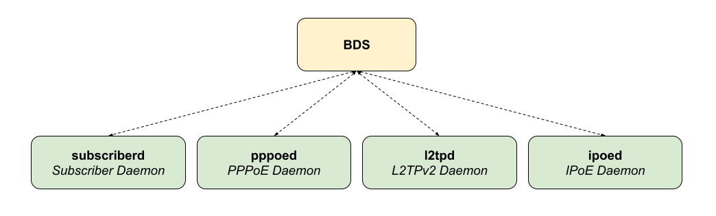
The subscriber daemon (subscriberd) is the central application, keeping the current subscriber state as well as being responsible for Authentication, Authorization, and Accounting (AAA).
-
subscriberd is for subscriber management and AAA (which can be local, through RADIUS, or other methods)
-
pppoed is to handle PPPoE and PPP sessions
-
l2tpd is for L2TPv2 tunnel and session handling
-
ipoed is for IPoE (IP-over-Ethernet aka DHCP) subscriber handling
This document describes the RBFS subscriber management implementation and configuration. The term subscriber describes an access user or session from a higher level decoupled from underlying protocols like PPPoE or IPoE.
Subscribers in RBFS can be managed locally or remotely via RADIUS. Each subscriber is uniquely identified by a 64-bit number called subscriber-id.
Remote Authentication Dial-In User Service (RADIUS)
Remote Authentication Dial-In User Service (RADIUS) is a networking protocol that provides centralized Authentication, Authorization, and Accounting (AAA) management for all types of subscribers (PPPoE, or IPoE). RADIUS servers can perform as authentication and accounting servers or change of authorization (CoA) clients. Authentication servers maintain authentication records for subscribers.
The subscriber daemon requests authentication in RADIUS access-request messages before permitting subscribers access. Accounting servers handle accounting records for subscribers. The subscriber daemon transmits RADIUS accounting-start, interim, and stop messages to the servers. Accounting is the process of tracking subscriber activity and network resource usage in a subscriber session. This includes the session time called time accounting and the number of packets and bytes transmitted during the session called volume accounting. A RADIUS server can behave as a change of authorization (CoA) client, allowing dynamic changes for subscriber sessions. The subscriber daemon supports both RADIUS CoA messages and disconnects messages. CoA messages can modify the characteristics of existing subscriber sessions without loss of service, disconnect messages can terminate subscriber sessions. Each RADIUS request from the subscriber daemon includes the RADIUS accounting-session-id attribute (type 44) with a format that is configurable in the AAA configuration profile and includes at least the subscriber-id to identify the corresponding subscriber. The default format (<subscriber-id>.<timestamp>) includes also a Unix timestamp to ensure that the tuple of NAS-Identifier (e.g. hostname) and Accounting-Session-Id is global and unique to be usable as a key in RADIUS databases.
Additionally, to subscriber-id and accounting-session-id each subscriber consists also of a subscriber-ifl build based on
physical port information and subscriber-id (ifp: ifp-0/0/1 and
subscriber-id: 72339069014638610 → subscriber-ifl: ppp-0/0/1/72339069014638610)
which is required as a handle in the RBFS forwarding infrastructure.
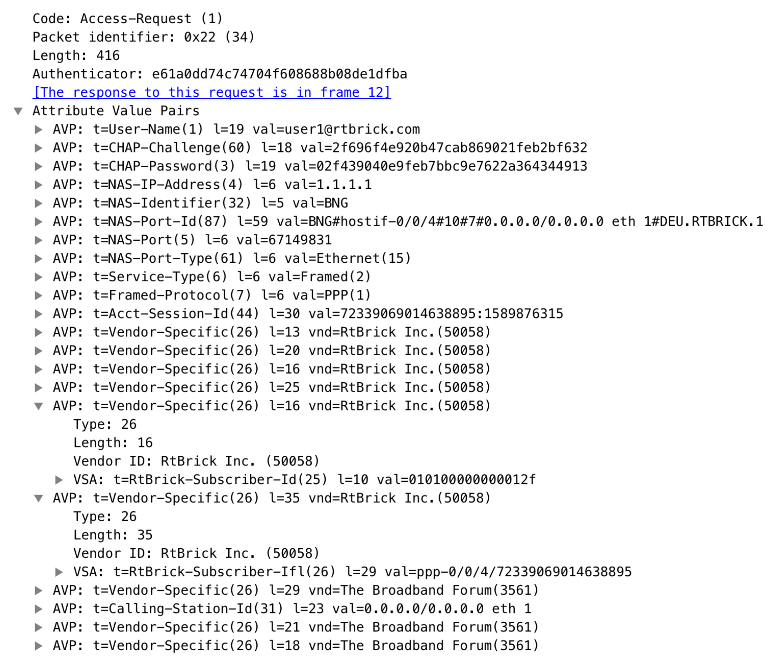
| The subscriber-id is an unsigned 64bit integer which is shown as a hex number in Wireshark. |
Each subscriber is formed based on configuration profiles and individual settings retrieved via RADIUS. Conflicts between RADIUS-defined attributes and profile attributes are solved by prioritizing those received from RADIUS which is common best practice for broadband access concentrators. New subscribers are signalled via RADIUS access request and either accepted by RADIUS access-accept or rejected by RADIUS access-reject message from the RADIUS server. The RADIUS access-accept includes all attributes required to form the subscriber like IP addresses, DNS servers, and referenced configuration profiles. Some of those attributes can be changed by RADIUS dynamically using CoA requests without disconnecting the subscriber.
RADIUS Accounting
A RADIUS Acct-Status-Type attribute is used by the RADIUS client (subscriber daemon) to mark the start of accounting (for example, upon booting) by specifying Accounting-On and to mark the end of accounting (for example, just before a scheduled reboot) by specifying Accounting-Off. This message is often used by RADIUS servers to automatically close/terminate all open accounting records/sessions for the corresponding client, and therefore must not be sent to servers belonging to a profile that was already used/started for accounting.
Per default, the assumption is that all servers referenced by a RADIUS profile share the same states and therefore accounting-on must be only sent to one of those before the first accounting-start is sent.
RADIUS Accounting-On/Off messages are optionally enabled in the RADIUS profile configuration ([RADIUS Profile Configuration]) using the accounting-on-off attribute. The additional attribute accounting-on-wait prevents any new session until accounting has started meaning that the Accounting-On response is received.
| Accounting-Off is currently not implemented! |
RADIUS accounting requests are often used for billing and therefore should be able to store and retry over a more extended period (commonly up to 24 hours or more) which can be optionally enabled in the RADIUS profile configuration using the accounting-backup attribute. The maximum backup accounting hold time in seconds is defined in the attribute accounting-backup-max.
RADIUS Redundancy
It is possible to configure multiple RADIUS authentication and accounting servers for redundancy and or load-balancing.
The following two algorithms are supported:
-
DIRECT (default): Requests are sent to the same server where the last request was sent. If the subscriber daemon receives no response from the server, requests are sent to the next server.
-
ROUND-ROBIN: Requests are sent to the server following the one where the last request was sent. If the subscriber daemon router receives no response from the server, requests are sent to the next server.
PPP over Ethernet (PPPoE)
PPP over Ethernet (PPPoE) is the common standard for internet access in the market.
| Currently, RBFS only supports PPPoE subscriber sessions with EtherType 0x8100 (802.1Q); it does not support EtherType 0x88a8 (802.1ad). |
PPPoE Session-Id
As defined in RFC2516, the PPPoE session-id field is an unsigned 16-bit number with the reserved values 0 for PADI/PADO and 65535 for future use. The session-id will be guaranteed unique per broadcast domain (IFP and VLANs) and client MAC address, but either not unique per device or app instance. The session-id changes every time the session is reconnected.
PPPoE Service-Name
The last service name from the request (PADI or PADR) is internally ignored but copied to the response (PADO or PADS). If the request does not include any service name, the response includes the default service name access for compatibility with some clients like Linux pppd.
PPPoE AC-Cookie
This TAG is actually used to aid in protecting against denial-of-service attacks, but it is primarily used in RBFS to decide if a received PADR is a retry for an already answered (PADS send) one. The value itself is unpredictable and generated securely but it does not protect from reply attacks.
If a client receives this TAG in PADO, it MUST return the TAG unmodified in the following PADR. The TAG_VALUE is binary data of any value and length and is not interpreted by the Host.
The AC-Cookie is generated based on 8-bit salt followed by MD5 hash of salt, client MAC and dynamic PPPoE cookie secret.
    0                   1                   2
    0 1 2 3 4 5 6 7 8 9 0 1 2 3 4 5 6 7 8 9 0 1 2 3 4
    +-+-+-+-+-+-+-+-+-+-+-+-+-+-+-+-+-+-+-+-+-+-+-+-+
    | SALT          | MD5                           |
    +-+-+-+-+-+-+-+-+-+-+-+-+-+-+-+-+-+-+-+-+-+-+-+-+
The PPPoE cookie secret is randomly generated during the PPPoE daemon startup.
The AC-Cookie in the PADR creating the session is stored in the PPPoE PPP session object. For any received PADR it can be checked if there is a session on the same broadcast domain (IFP and VLAN’s) and MAC with the same AC-Cookie. In this case, the PADS is just retried.
If the broadcast domain and MAC is equal but AC-Cookie is different, this PADR must be considered as a new request.
This allows to separate two different PPPoE sessions on the same VLAN from the same MAC as frequently used by some service providers.
PPPoE Session Limit
A customer line is typically represented by one (single-tagged) or two VLAN (double-tagged) on a physical interface with a limitation to one session, which is also called the 1:1 VLAN mode.
In some cases, the customer CPE will set up multiple PPPoE sessions on a single VLAN which requires MAC limitations greater than one but less or equal to the per VLAN limitation.
Therefore RBFS supports two different session limitations in the access interface configuration ([Access Interface Configuration]), one per VLAN (max-subscribers-per-vlan) and an additional per client MAC address (max-subscribers-per-mac) both set to 1 per default as required for 1:1 VLAN mode.
The limitation of sessions per client MAC address must be less or equal the sessions per VLAN and the default set to one for both limits.
PPPoE 1:1 and N:1 Support
RBFS supports both 1:1 VLAN (VLAN Per Subscriber) and N:1 VLAN (shared VLAN) models for subscriber traffic for PPPoE subscribers.
1:1 VLAN (VLAN-per-subscriber) Model
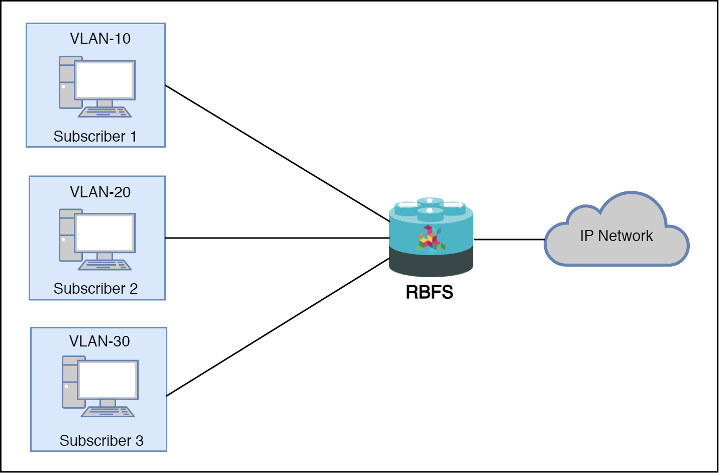
In the 1:1 VLAN model, there is a unique dedicated customer VLAN for a subscriber, that is one VLAN per Subscriber. This model establishes a unique path between each subscriber interface and the router for data transmission by providing traffic separation for every subscriber.
1:1 model operations are relatively simple as it provides one-to-one mapping of specific VLANs to specific subscribers. New services can be added easily without affecting other subscribers and services with this model. However, in a large-scale deployment, this model demands highly scalable and robust routers that can manage many hundreds of VLANs.
The following diagram shows a dedicated customer VLAN for a subscriber, that is, one VLAN per Subscriber.
N:1 VLAN (Shared VLAN) Model
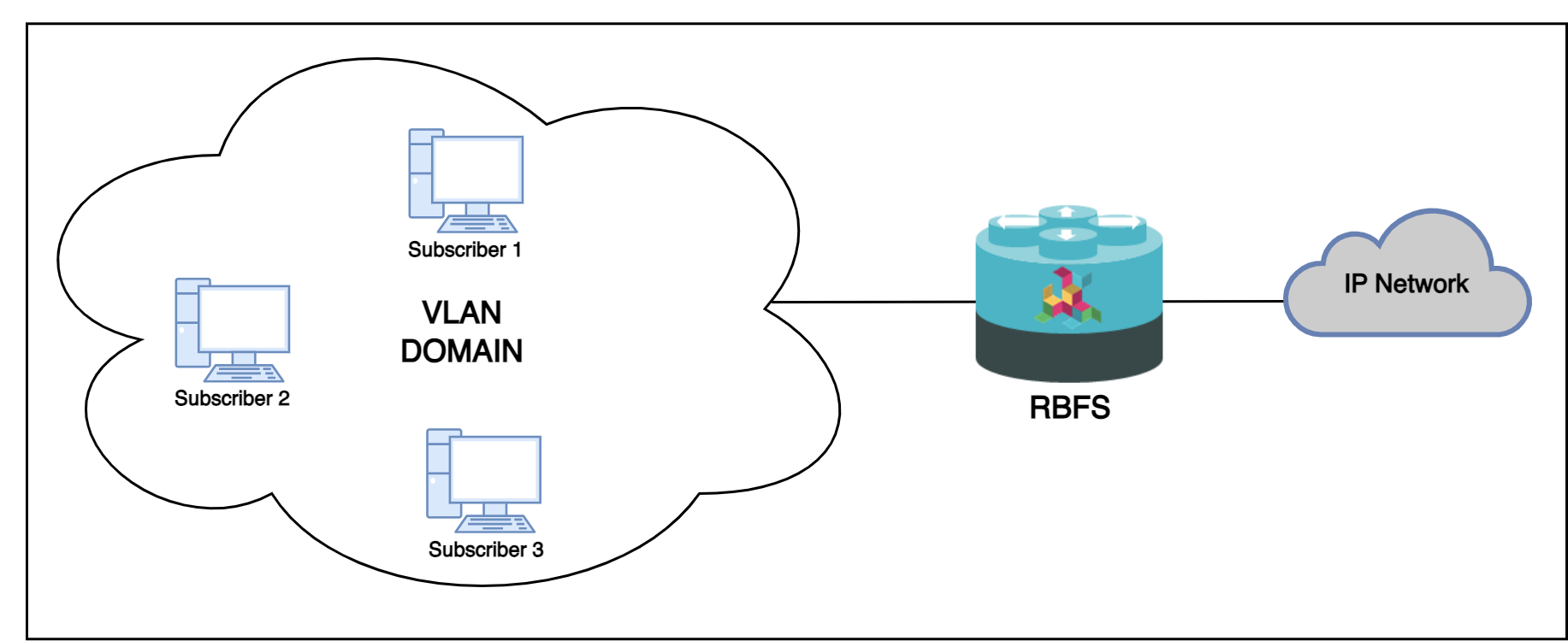
The Shared VLAN model provides many-to-one (N:1) subscriber-to-service connectivity. This model provides a single VLAN to many subscribers. Unlike in the 1:1 model, in which the VLAN is dedicated to a customer, N:1 provides a shared VLAN to many subscribers, and this VLAN carries all types of service (i.e., data, voice, video, etc.). One disadvantage of shared VLAN is the lack of logical isolation between user sessions at the VLAN level.
The following diagram shows a single VLAN that is connected to many subscribers.
PPPoE MTU Profiles
The PPP protocol allows each endpoint to negotiate a maximum receive unit (MRU). This MRU is applied as the maximum transmission unit (MTU) on the other end of the PPP connection. Each endpoint negotiates its own MRU with the other peer. Thus using a different MTU per direction is not uncommon for PPP, even if not desired.
Bare metal switch hardware is typically limited in the number of supported MTU values.
So RBFS has introduced the concept of MTU profiles with different types like physical,
ip or pppoe. The last one is reserved for use with PPPoE sessions and applies to
IPv4 and IPv6 traffic.
supervisor@switch: cfg> show config forwarding-options mtu-profile
{
  "rtbrick-config:mtu-profile": [
    {
      "mtu-profile-name": "IP-MTU-1500",
      "size": 1500,
      "type": "ip",
      "action": "redirect-to-cpu"
    },
    {
      "mtu-profile-name": "IP-MTU-9202",
      "size": 9202,
      "type": "ip",
      "action": "drop"
    },
    {
      "mtu-profile-name": "PPPoE-MTU-1320",
      "size": 1320,
      "type": "pppoe",
      "action": "redirect-to-cpu"
    },
    {
      "mtu-profile-name": "PPPoE-MTU-1456",
      "size": 1456,
      "type": "pppoe",
      "action": "redirect-to-cpu"
    },
    {
      "mtu-profile-name": "PPPoE-MTU-1472",
      "size": 1472,
      "type": "pppoe",
      "action": "redirect-to-cpu"
    },
    {
      "mtu-profile-name": "Port-MTU-9216",
      "size": 9216,
      "type": "physical",
      "action": "drop"
    },
    {
      "mtu-profile-name": "__default_pppoe__",
      "size": 1492,
      "type": "pppoe",
      "action": "redirect-to-cpu"
    }
  ]
}
A configured size of 1492 bytes limits the size of the IPv4 or IPv6 header plus payload.
| The physical access interface should be configured with an MTU profile large enough to serve all PPPoE MTU profiles, including the additional overhead for PPPoE and VLAN headers. Further details about interface MTU profiles can be found in the Interfaces Configuration Guide. |
The action could be either drop or redirect-to-cpu. The action drop silently discards
all oversized packets. The action redirect-to-cpu punts oversized packets to the CPU where
those could be either fragmented or dropped with ICMP response.
The Q2C platform supports up to 8 MTU profiles in total. The amount of pppoe profiles is limited to 6
including the default profile _default_pppoe_. The default profile can’t be deleted but overwritten
to change size and action.
supervisor@switch: cfg> show config forwarding-options mtu-profile __default_pppoe__
{
  "rtbrick-config:mtu-profile": [
    {
      "mtu-profile-name": "__default_pppoe__",
      "size": 1492,
      "type": "pppoe",
      "action": "redirect-to-cpu"
    }
  ]
}
The command show pppoe mtu-profile lists all PPPoE MTU profiles
in increasing order, with two statistics about the exact and best match.
supervisor@switch: op> show pppoe mtu-profile
Profile                MTU      Exact Match      Best Match
PPPoE-MTU-1320         1320     0                0
PPPoE-MTU-1456         1456     0                0
PPPoE-MTU-1472         1472     0                0
__default_pppoe__      1492     0                0
If a client requests an MRU via PPP LCP Configure-Request, this value is used to search for an appropriate MTU profile. This is done by iterating over the ordered list of MTU profiles, as long as the received MRU is greater than the MTU size. If the requested MRU is found in the list of MTU profiles, the exact match counter is incremented, and the MRU is accepted.
In case the requested MRU is not found, the last MTU profile found is selected
and the best match counter is incremented. The selected MTU is then offered to the
client via PPP LCP Configure-Nak. If the offered MRU is not accepted by the client
after three offers, a fallback profile is applied. This means that the requested MRU
from the client is accepted, but the largest pppoe MTU profile is applied.
This algorithm was built to ensure most client compatibility.
Let’s assume a client requests the MRU 1482, but only profiles for 1472 and 1492 are configured. In this case, 1472 is offered as the best match via PPP LCP Configure-Nak. The client could either accept the offer by sending a PPP LCP Configure-Request with the MRU 1472 or try again with the original value of 1482. This is repeated up to three times before the fallback profile is applied. In this case, the client MRU of 1482 is accepted but the maximum MTU of 1492 is applied. The majority of CPE devices support TCP MSS clamping using the negotiated MRU of 1482. So at least TCP traffic is still limited to the negotiated MRU. This is the reason for applying a larger MTU profile as the fallback profile. It’s also common that a CPE still accepts packets larger than the negotiated MRU.
The exact and best match counters can be used by operators to verify if the configured MTU profiles fit their environment or should be adopted.
The negotiated MRU and applied MTU can be verified with the following command for every single PPPoE session.
user@switch: op> show pppoe session 72339069014638648 detail
Subscriber-Id: 72339069014638648
    State: ESTABLISHED
    ...
    PPP LCP:
        ...
        MRU: 1492 Peer: 1492
        MTU: 1492 Profile: __default_pppoe__
    ...
For L2TPv2 tunneled PPPoE sessions, the MTU is enforced by the LNS. It’s usual behavior that the LNS renegotiates the MTU. So LAC may not know the actual MTU. This is the reason why RBFS does not apply an MTU profile for such sessions.
RBFS overwrites the selected MTU profile with default_l2tp for L2TPv2 sessions. This profile must
be explicitly created, otherwise it is ignored. The action must be drop because ICMP or fragmentation
is not supported for tunneled sessions.
supervisor@switch: cfg> show config forwarding-options mtu-profile __default_l2tp__
{
    "rtbrick-config:mtu-profile": [
      {
        "mtu-profile-name": "__default_l2tp__",
        "size": 1492,
        "type": "pppoe",
        "action": "redirect-to-cpu"
      }
    ]
  }
This configuration allows to optionally enforce an MTU on LAC if needed.
PPPoE VLAN Profiles
This chapter describes the VLAN profile feature. If enabled for the access interface, then incoming sessions (e.g. PPPoE PADI/PADR) are not honored unless matching vlan-profile is found.
The VLAN profiles must be added to the table global.vlan.profile owned by PPPoE daemon.
All entries in this table are ephemeral and therefore lost after reboot or PPPoE daemon restart.
Example:
{
    "table": {
        "table_name": "global.vlan.profile"
    },
    "objects": [
        {
            "attribute": {
                "ifp_name": "ifp-0/1/2",
                "outer_vlan_min": 128,
                "outer_vlan_max": 128,
                "inner_vlan_min": 1,
                "inner_vlan_max": 4095,
                "access_profile_name": "access-profile-vlan"
            }
        }
    ]
}
PPPoE Dual-Stack IPv4/IPv6 with DHCPv6
The whole IPv6 control plane of a PPPoE session like ICMPv6 router-solicitation (RS), ICMPv6 router-advertisement (RA) and DHCPv6 is handled in the PPPoE daemon (pppoed).
The PPPoE daemon handles received router solicitations by responding with router advertisements and is sending frequent router advertisements based on configured intervals.
The other-config flag in the router-advertisement is automatically set if DHCPv6 is enabled for this particular subscriber. This flag signals that there is more information available via DHCPv6.
DHCPv6 over PPPoE is different to DHCPv6 over Ethernet because of the special characteristics of point-to-point protocols. DHCPv6 over PPPoE is supporting delegated IPv6 prefixes (IA_PD) and DNS options only. Unsupported IA options (IA_NA and IA_TA) or options that can be served will be rejected with status code options as defined per RFC.
The delegated IPv6 prefix served by DHCPv6 will be assigned to the subscriber via RADIUS
or local pool regardless of the protocols negotiated with the client. DHCPv6 was primarily
designed for use in Ethernet networks. The fact that Ethernet is connectionless requires
that DHCPv6 servers must manage releases for the clients and free them automatically if a lease
expires. Such extensive release management is not needed for connection-oriented protocols
like PPPoE where addresses are assigned to the PPPoE session. This fact allows to
implementing DHCPv6 nearly stateless on the server side by just tracking if an assigned prefix
is assigned or released. This is tracked in the attribute ipv6pd_negotiated of the PPPoED/SubscriberD (global.ppp.1.subscriber.result) result object and copied to the
actual subscriber object (local.access.subscriber). As this use case is covered by PPPoE, there is no lease expiry implemented.
The delegated-prefix is added to the subscriber-ifl only if negotiated and removed if not negotiated. The presence of delegated prefix in the subscriber-ifl is used by IFMD to add or remove the forwarding entry.
If DHCPv6 is enabled but no delegated prefix provided, only DNS is served in response if available.
PPPoE DHCPv6 Server DUID
The DHCPv6 server identifier DUID is generated based on IP6CP negotiated interface-identifier as shown below:
    0                   1                   2                   3
    0 1 2 3 4 5 6 7 8 9 0 1 2 3 4 5 6 7 8 9 0 1 2 3 4 5 6 7 8 9 0 1
    +-+-+-+-+-+-+-+-+-+-+-+-+-+-+-+-+-+-+-+-+-+-+-+-+-+-+-+-+-+-+-+-+
    |     DUID-Type 3 (DUID-LL)     |    hardware type 27 (EUI64)   |
    +-+-+-+-+-+-+-+-+-+-+-+-+-+-+-+-+-+-+-+-+-+-+-+-+-+-+-+-+-+-+-+-+
    |                      interface-identifier                     |
    |                                                               |
    +-+-+-+-+-+-+-+-+-+-+-+-+-+-+-+-+-+-+-+-+-+-+-+-+-+-+-+-+-+-+-+-+
Layer Two Tunneling Protocol (L2TPv2)
This chapter describes the RtBrick Layer Two Tunneling Protocol (L2TPv2) implementation. This document describes also the corresponding configuration ([Configuration Commands]) and operations ([Operations]) for PPPoE access services with PPP tunneling using the Layer Two Tunneling Protocol version 2 (L2TPv2) on RtBRick FullStack (RBFS).
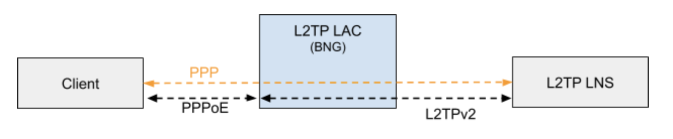
Typically, a user obtains a Layer 2 (L2) point-to-point connection to a Broadband Network Gateway (BNG) using the PPPoE protocol as described in RFC 2516 and runs PPP over that connection. In the most common case, the L2 termination point and PPP session endpoint reside on the same physical device. Tunneling protocols, such as L2TPv2 provide a dynamic mechanism for extending PPP by allowing the L2 and PPP endpoints reside on different devices that are interconnected by an IP network. This separation allows the actual processing of PPP packets to be divorced from the termination of the L2 circuit. The L2TP access concentrator (LAC) physically terminates the L2 connection and tunnels the PPP packets across an IP network to the L2TP network server (LNS). The LNS then terminates the logical PPP connection.
| RFC and draft compliance are partial except as specified. |
L2TP LAC
The L2TP Access Concentrator (LAC) is a node that acts as one side of an L2TP tunnel endpoint, and is a peer to the L2TP Network Server L2TP LNS. The LAC sits between a LNS and a remote system, and forwards packets to and from each.
L2TP LNS
The L2TP Network Server (LNS) is a node that acts as one side of an L2TP tunnel endpoint and is a peer to the L2TP Access Concentrator L2TP LAC. The LNS is the logical termination point of a PPP session that is being tunneled from the remote system by the LAC.
| The LNS role is currently not supported! |
L2TP Tunnel Selection
Each new session creates a session request object (local.l2tp.session.request) to track the tunnel selection progress, the currently selected ones, and which are already tried. This object is automatically deleted if the session setup is successful.
All tunnels in state DEAD are skipped in the tunnel selection but considered at the end if no other tunnels are available. Tunnels with a session limit reached are not considered for further sessions. To select a tunnel, the L2TP daemon first generates list of preferred tunnels based on tunnel preference, where the lowest value has the highest priority. The configured L2TP tunnel selection algorithm decides how to select a tunnel out of the remaining tunnels with the same preference. The RANDOM algorithm selects the tunnel randomly whereas BALANCED selects the least filled tunnel based on a number of sessions.
Following the L2TP tunnel pool order/priority in case, there are multiple pools available for a single subscriber:
-
RADIUS defined tunnel (RFC2866)
-
RADIUS VSA (RtBrick-L2TP-Pool) or local user profile
-
L2TP configuration profile
L2TP Control Channel
The control channel is responsible for the orderly passing of control messages between the tunnel endpoints and acts as a transport layer for reliable delivery of control messages and tunnel keep alive services for the tunnel.
Each L2TP tunnel is split into the actual tunnel object with all the information exchanged during tunnel establishment plus the FSM state and a separate control channel with the sequence numbers, window size, and thresholds changed with every sent and received packet.
RBFS sent a ZLB ACK only if there are no further messages waiting in queue for that peer, as well as to acknowledge multiple packets at once.
The HELLO keep-alive messages are also part of the control channel and only send if there is no other message sent if the queue is empty and no other message send during the hello interval.
L2TP Access Line Information (RFC5515)
Connect-Speed-Update-Notification (CSUN)
The Connect-Speed-Update-Notification (CSUN) is an L2TP control message sent by the LAC to the LNS to provide transmit and receive connection speed updates for one or more sessions.
| This implementation will send one CSUN request per session! |
CSUN requests are disabled per default and can be enabled in the L2TP profile ([L2TP Profile Configuration]).
CSUN messages are defined in RFC5515, which is not widely supported. Therefore those messages are marked as not mandatory in RBFS to allow interwork with LNS servers not supporting RFC5515.
RFC2661:
The Mandatory (M) bit within the Message Type AVP has special
meaning. Rather than an indication of whether the AVP itself
should be ignored if not recognized, it is an indication as to
whether the control message itself should be ignored. Thus, if the
M-bit is set within the Message Type AVP and the Message Type is
unknown to the implementation, the tunnel MUST be cleared.  If the
M-bit is not set, then the implementation may ignore an unknown
message type.
| RFC and draft compliance are partial except as specified. |
Connect-Speed-Update-Request (CSURQ)
The Connect-Speed-Update-Request (CSURQ) is an L2TP control message sent by the LNS to the LAC to request the current transmission and receive connection speed for one or more sessions.
| Sending or responding to CSURQ requests is currently not supported! |
Access Line Information L2TP Attribute Value Pair Extensions
The corresponding access line information for a subscriber is included in the ICRQ message as defined in RFC5515.
Connect Speed Values
The default value for TX and RX Connect Speed is set to 1000000000 (1G) which is replaced by the actual data rate upstream/downstream of the corresponding access line information object or directly set using the RADIUS attributes RtBrick-L2TP-Tx-Connect-Speed (42) and RtBrick-L2TP-Rx-Connect-Speed (43).
IPoE
IP-over-Ethernet (IPoE) is a popular alternative to PPPoE based access using DHCP for IPv4 and DHCPv6 for IPv6 where both protocols are handled in the IPoE daemon (ipoed).
IPoE subscribers are identified by IFP, optional VLAN and client MAC address.
The dynamic creation of IPoE subscribers is triggered by the first DHCPv4 discovery or
DHCPv6 solicit request received. Any response is postponed until the subscriber is
successfully authenticated using known authentication methods like none, local
or RADIUS. For DHCP mode server all addresses are assigned during authentication to the subscriber and used by DHCPv4 and DHCPv6 to handle client requests.
IPoE subscribers will be terminated automatically if all protocol bindings are deleted.
IPoE 1:1 VLAN Support
RBFS supports 1:1 VLAN (VLAN Per Subscriber) model for subscriber traffic for IPoE subscribers. In the 1:1 VLAN model, there is a unique dedicated customer VLAN for a subscriber, that is one VLAN per Subscriber. This model establishes a unique path between each subscriber interface and the router for data transmission by providing traffic separation for every subscriber.
The following diagram shows a dedicated customer VLAN for a subscriber, that is, one VLAN per Subscriber.
IPoE Session Limit
A customer line is typically represented by one (single-tagged) or two VLAN (double-tagged) on a physical interface with a limitation to one subscriber, which is also called the 1:1 VLAN mode.
IPoE subscribers are implicitly limited to max one per MAC address, as client MAC address is used as part of the key to identify subscribers.
IPoE Username
For each IPoE subscriber, a username is generated automatically using
the client’s MAC address followed by @ipoe.
Example: fe:08:e8:ea:1d:32@ipoe
IPoE DHCPv6 Server DUID
The generated DHCPv6 server identifier DUID is from type 3 (DUID-LL) with hardware type 27 (EUI64) and IFP MAC address to derive the EUI64 interface identifier.
    0                   1                   2                   3
    0 1 2 3 4 5 6 7 8 9 0 1 2 3 4 5 6 7 8 9 0 1 2 3 4 5 6 7 8 9 0 1
    +-+-+-+-+-+-+-+-+-+-+-+-+-+-+-+-+-+-+-+-+-+-+-+-+-+-+-+-+-+-+-+-+
    |     DUID-Type 3 (DUID-LL)     |    hardware type 27 (EUI64)   |
    +-+-+-+-+-+-+-+-+-+-+-+-+-+-+-+-+-+-+-+-+-+-+-+-+-+-+-+-+-+-+-+-+
    |                      interface-identifier                     |
    |                                                               |
    +-+-+-+-+-+-+-+-+-+-+-+-+-+-+-+-+-+-+-+-+-+-+-+-+-+-+-+-+-+-+-+-+