HQoS Features
This chapter explains the following topics:
Priority Propagation
Hierarchical QOS (HQoS) on RBFS is implemented by connecting or chaining queues to scheduler elements (Q — > SE), scheduler elements to each other (SE — > SE), and scheduler elements to ports (SE — > PORT). Each scheduler element can have different child connection points based on types described in the section Scheduler.
This means that sched_0 in the example below is not scheduling between the attached queues, but between the different child connection points SP0 to SP3. The scheduler element sched_0 cannot differentiate between Q1 and Q2 in this example because both are connected to SP2.
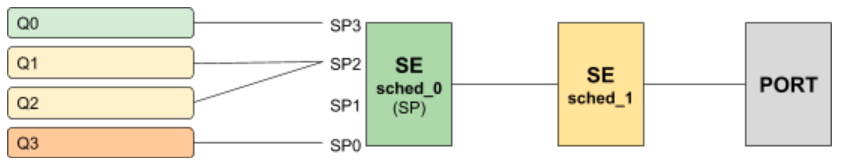
Without priority propagation, each scheduler element can have multiple child connection points but just one parent connection point. Therefore traffic leaving a scheduler element cannot be differentiated by the parent scheduling element. The parent scheduler element sched_1 receives the traffic from sched_0 on the selected child connection point. As already mentioned scheduling within a scheduler element happens between child connection points. Second, a scheduler element has only one parent connection point which can be connected to a child connection point of another scheduler element (output of sched_0 → input of sched_1). This results in the situation that all traffic from this SE is handled equally regardless of the queue. This may lead to dropped priority traffic like voice or control traffic in case of congestion in parent elements. For example, if sched_1 has a shaping rate lower than the one of sched_0, it will drop traffic unaware of its original priority.
This problem is addressed with priority propagation which is enabled by default.
With priority propagation, the scheduler elements operate in a dual-flow mode with high and low-priority flows. The credits generated from the physical interface will be consumed by all attached high-priority flows first and only the remaining credits will be available for low-priority flows. In this mode, an implicit FQ element is created for each scheduler element. All queues assigned to low-priority flow will be attached to this element.
An additional composite option of the scheduler element allows also the differentiation between multiple low-priority queues if required. This composite type is created implicitly and does not need to be configured.
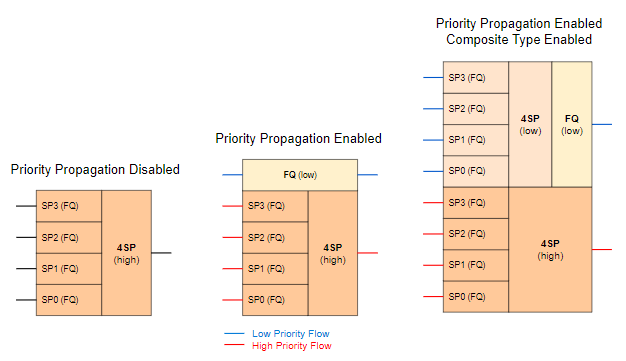
Without priority propagation enabled, each scheduler element consumes only one scheduler resource compared to two elements if enabled. The composite type consumes three scheduler elements.
With priority propagation disabled, all traffic is considered as high-priority flow.
Now for each queue, we can select if connected to high-priority or low-priority flow where high-priority flow is selected per default if not explicitly mentioned.
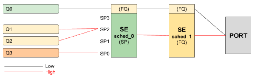
Assuming the example as before but with priority propagation and Q0 assigned to low-priority flow and Q1 - Q3 assigned to high-priority flow.
The figure below shows a typical multi-level QoS configuration without priority propagation on the left and with priority propagation on the right side.
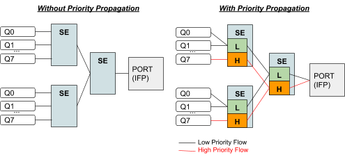
The credits generated from the physical interface will be consumed by high-priority flow first and the remaining credits will be available for low-priority flow. The high-flow traffic at any one element is scheduled based on type and connection point. Between schedulers, it depends on how they are connected to the parent scheduling element. Per default all levels there is FQ for low and FQ for high-priority flows. The port scheduler is also FQ.
In this mode, each shaper supports two different rates for low and high-priority where the actual shaper rate is the sum of low and high-priority rates. If low-priority rate is zero, this flow is only served if high-priority flow is not consuming all credits. An example might be a high rate of 9Mbps and low rate of 1m which results in max 10Mbps for low-priority flow if high-priority flow is not consuming any packets but at least 1m is ensured.
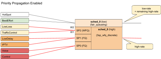
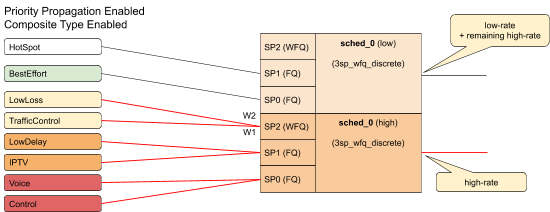
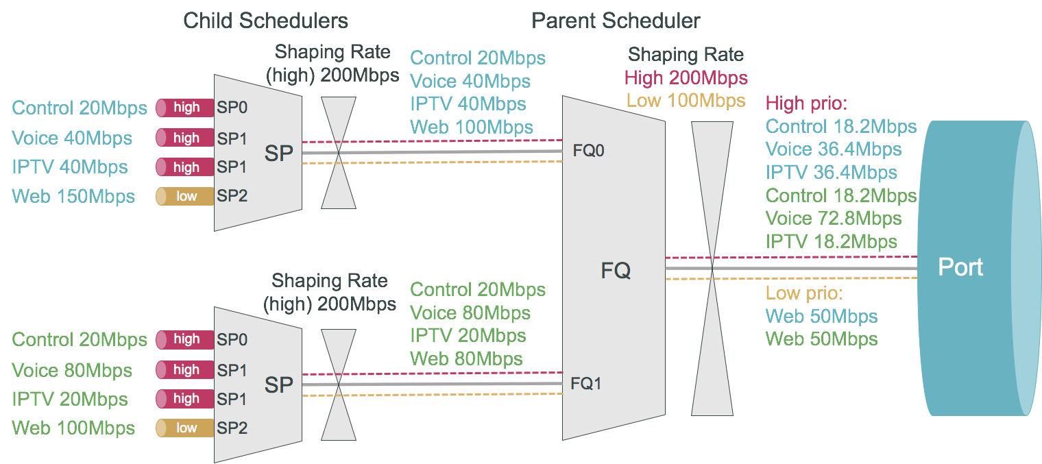
The following example shows a typical access service provider configuration with priority propagation enabled with and without composite type.
Simple Priority Propagation Scheduling Example
Without priority propagation, the parent scheduler drops traffic equally from all classes as it is unaware of priorities:
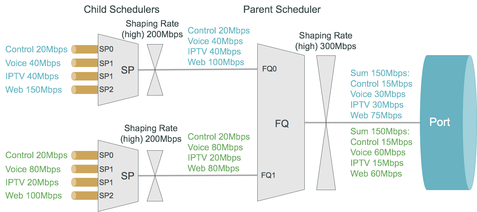
With priority propagation, the parent scheduler serves high-priority flows first as shown in the figure below:

With priority propagation and dual-flow shaping, the parent scheduler serves high-priority flows first up to the high-flow shaping rate:
Behavior Aggregate (BA) Classifier
Classifiers assign the class to which a packet belongs. BA classification is performed on the ingress and maps incoming packet codepoint to a predefined class. BA Classification relies upon markings (that is, codepoint) placed in the headers of incoming packets:
-
IEEE 802.1p: Priority - 3 bits
-
IPv4: Type of Service byte (ToS) - 8 bits.
-
IPv6: Traffic Class (TC) - 8 bits.
-
MPLS: Experimental bits (EXP) - 3 bits.
|
Classifier configuration has the following guidelines and limitations:
-
For IPv4: Only ToS-based classification is possible. DSCP-based classification is not possible.
-
For IPv6: Only TC-based classification is possible. DSCP-based classification is not possible.
-
For EXP classification, RBFS uses the uniform mode to copy MSB 3-bits from the DSCP to EXP field at the time of MPLS encapsulation at the remote box.
-
IPv4/IPv6 Classifiers do not match on labeled traffic. MPLS Classifier is required for the same.
|
Ingress Remarking
Ingress remarking is achieved by configuring the “remark-codepoint” field in the Classifier. Ingress remarking rewrites the IPv4-ToS or IPv6-TC field of the incoming packet at the ingress side with configured remark-codepoint. Note that the ingress remarking is not supported for BA Classifier with MPLS-EXP match-type.
Multifield (MF) Classifier
| Multifield Classifier is currently not supported on Edgecore AS7316-26XB platform. |
Multifield (MF) classifiers assign the class to which a packet belongs based on multiple fields. Unlike the BA classifier, where only CoS fields are used for classification, the MF classifier additionally uses the following fields:
-
class: traffic class of the packet (class-0 to class-7) set by prior BA classifier
-
source prefix: source IPv4 or IPv6 prefix
-
destination prefix: destination IPv4 or IPv6 prefix
-
protocol: UDP or TCP
-
source port: UDP or TCP source port
-
destination port: UDP or TCP destination port
-
qos markings: IPv4 TOS or IPv6 TC header value
The actions supported by a multifield classifier are:
-
class: traffic class to be set (class-0 to class-7)
-
Remark codepoint: remark codepoint for ingress remarking
RBFS treats all the incoming IPv4-TOS or IPv6-TC QoS field values in the incoming packet as untrusted. So a user is required to set action-remark-codepoint in the MF Classifier configuration to mark the QoS bits in the IP header of the outgoing packet. If action-remark-codepoint is not configured in the MF Classifier, the default value 0 shall be marked in the packet.
|
The multifield classifiers can be bound globally (global.qos.global.config) or via QoS profile (global.qos.profile.config). The global multifield classifier applies to all traffic from any instance or interface. The multifield classifier assigned via the QoS profile applies only to ingress traffic received on the interface where the profile is bound to it.
The multifield classifier is processed after BA classification which allows it to match on selected class from BA classification or to change the assigned class by more granular match conditions. Both classification stages (BA and MF) are optional, they can be combined together or used alone, controlled by configuration.
Multifield classifiers can’t be bound to MPLS core interfaces. Therefore, the downstream traffic (from core to subscriber) should be classified via global multifield classifier, while upstream traffic (from subscriber to core) can be classified via multifield classifier from the QoS profile, which is instantiated per subscriber with an implicit match on ingress logical interface (InLIF).
|
Match MPLS traffic
If MF Classifier is to be applied for MPLS traffic (that is, DOWNSTREAM traffic), match mpls traffic has to be configured in the MF ACL. If not configured, traffic may or may-not match the MF ACL entry in the h/w.
Ingress Remarking
Ingress remarking is achieved by configuring the “action remark-codepoint” in the MF Classifier. Ingress remarking rewrites the IPv4-ToS or IPv6-TC field of the incoming packet at the ingress side with configured remark-codepoint.
RADIUS Controlled Dynamic MF Classifier
As described for RBFS RADIUS Services document dynamic MF Classifier mapping is supported. The dynamic MF Classifier when configured override the MF Classifier mapped via QoS profile for the corresponding subscriber but not other subscribers.
For information about configuring MF Classifier, see [mf_classifier_configuration].
Remarking
The packet markers set the codepoint in a packet to a particular value, adding the marked packet to a particular behavior aggregate. When the marker changes the codepoint in a packet, it "remarks" the packet. The codepoint in a packet can be IPv4-ToS, IPv6-TC, MPLS-EXP, or IEEE 802.1p field.
The following remarking options are supported in RBFS:
-
IEEE 802.1p : Priority - 3 bits.
-
IPv4: Type of Service byte (ToS) - 8 bits.
-
IPv6: Traffic Class (TC) - 8 bits.
-
MPLS-IPv4: MPLS Experimental bits (EXP) - 3 bits.
-
MPLS-IPv6: MPLS Experimental bits (EXP) - 3 bits.
IPv4/v6 and IEEE 802.1p remark-map are applied on an interface - subscriber-ifl or l3ifl using Profile Name.
MPLS-IPv4/v6 remark-map is applied either globally or per-instance (to support multiple VPN marking schemes) using Remark-Map Name.
In RBFS, remarking can be performed at the ingress or egress:
-
Ingress remarking is achieved by configuring the remark-codepoint field in the Classifier. Ingress remarking rewrites the IPv4-ToS or IPv6-TC at the ingress side with configured remark-codepoint. The configured remark-codepoint can be modified again at the egress side using remark-map. The ingress remarking is supported for IPv4, IPv6, and IEEE 802.1p BA classifiers.
-
Egress remarking is achieved by configuring the remark-map. Remark Map is the mapping of match-codepoint and color to remark-codepoint. Egress remarking helps to remark the IPv4-ToS / IPv6-TC field in the IP header, or to write the EXP field in the MPLS label(s), or to write the IEEE 802.1p field in the VLAN header.
Here Color is used to set different remark-codepoint for same match-codepoint based on color marked by the Policer (i.e. green or yellow). Color is a mandatory field in remark-map. To set the same remark-codepoint for a match-codepoint irrespective of color, we have to set color as “all”.
IPv4-ToS, IPv6-TC, or MPLS-EXP remarking:
-
If the remark-codepoint is not configured in the BA Classifier or there is no hit in MF Classifier, match-codepoint in the remark-map is the ToS/TC value of the incoming IP packet.
-
If the remark-codepoint is configured in the BA Classifier and there is no hit in the MF Classifier, match-codepoint is the same value as the remark-codepoint in the BA Classifier
-
Irrespective of the remark-codepoint configured in the BA Classifier, if there is a hit in the MF Classifier the match-codepoint is the same value as the action remark-codepoint (0 if no action remark-codepoint configured) in the MF Classifier.
IEEE 802.1p VLAN remarking:
|
L2BSA L2X VLAN Priority Remarking:
The L2BSA L2X VLAN priority remarking support for the platforms is as follows: Only A10NSP switches support VLAN operations, access-leaf is transparent.
-
Downstream Traffic (Remote ISP to Subscriber):
-
On A10NSP Switch:
-
The class derived from the VLAN Pbit Classifier is used to remark MPLS Exp and Outer VLAN IEEE-802.1 Pbit Value, inner VLAN Pbit is transparent.
-
-
On Q2C Access Leaf:
-
The received Outer VLAN IEEE-802.1 Pbit value is retained, explicit remarking at access-leaf is not supported.
-
-
-
Upstream Traffic (Subscriber to Remote ISP):
-
On Q2C Access Leaf:
-
To remark the outgoing packet, global MPLS Exp remark map can be used.
-
-
On A10NSP Switch:
-
To remark the outgoing packet, VLAN IEEE-802.1 Pbit remark map can be used.
-
-
For more information about L2BSA configurations, see the L2BSA Use Guide.
Policer
Policer defines the rate at which certain applications can access the hardware resource. So as to rate-limit the traffic from an application, policer hard-drops the unwanted packets in the ingress side.
In RBFS, policers support “two-rate, three-color” type in a 4-levels cascaded mode. This means that each policer level has two rates (CIR and PIR) and three colors (green, yellow and red) with two token buckets as shown below.
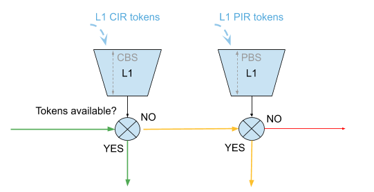
This means that traffic below CIR is marked green. Traffic above CIR but below PIR is yellow and above PIR is red. Traffic marked red will be dropped. Traffic marked yellow can be demoted by changing ToS, TC, or EXP using remark-map.
In 4 level cascade mode, unused tokens can be passed from higher priority levels to lower priorities where level 1 has the highest and level 4 has the lowest priority as shown in the figure below.
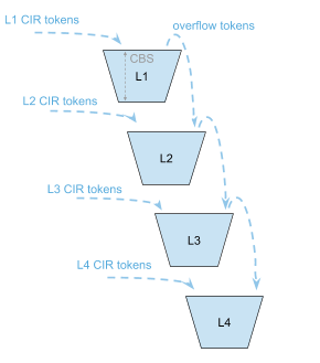
Therefore a lower level configured with CIR 0 can still serve traffic if higher priority levels are not consuming all available tokens.
The available tokens per level are calculated by remaining CIR credits from upper levels and additional credits based on configured CIR per level. Per default the resulting tokens are not limited. The optional max CIR rate attribute allows to limit the sum of tokens from CIR and upper levels. Let’s assume level 1 and 2 are both configured with a CIR of 2m. Without max CIR (default behaviour) level 2 can reach up to 4m (level 1 CIR plus level 2 CIR). This can be limited by max CIR (for example, 3m). Obviously max CIR is not relevant for level 1.
Example
| CIR | RX | TX | CIR | RX | TX | |
|---|---|---|---|---|---|---|
L1 |
4m |
1m |
1m |
4m |
1m |
1m |
L2 |
6m |
20m |
9m |
6m / max CIR 8 |
20m |
8m |
L3 |
0m |
20m |
0m |
0m |
20m |
1m |
L4 |
0m |
20m |
0m |
0m |
20m |
0m |
SUM |
10m |
61m |
10m |
10m |
61m |
10m |
-
Here,
mindicates Mbps (Megabits per second)
In columns 2 through 4 of the preceding example table, L1 consumes only 1m of the available 4m and passes the remaining 3m to L2 which adds an additional 6m based on their own configured CIR resulting in 9m.
In columns 5 through 7 of the preceding example table, L1 consumes only 1m of the available 4m and passes the remaining 3m to L2 which adds additional 6m based on their own configured CIR resulting in 9m. But because of the CIR limit set to 8m, only 8m of 9m can be used at this level. The remaining 1m is now passed to L3 which does not add additional CIR based credits. In both examples, L4 would be able to reach up to 10m if upper levels are not consuming credits.
RADIUS Controlled Dynamic Policer
The RBFS RADIUS services support dynamic policer rate updates. The dynamic policer rate when configured affects only the QoS instance of the corresponding subscriber but not other subscribers.
Class-Policer-Map
Since RBFS supports up to 8 classes but only four policer levels, there is a need to map multiple classes to the same policer level. A class-policer-map defines such mappings. Using class-policer-map configuration, one can map any class to any supported policer level (that includes mapping multiple or all classes to the same level). Similar to a policer, a class-policer-map is attached to a profile.
| If class-to-level mapping is not configured, no policing will be applied to the traffic for that class. |
Queueing
Queuing helps to drop unwanted traffic in advance at the ingress side in case of congestion. This is to ensure bandwidth for qualified services.
RBFS supports the following queueing techniques:
-
Tail Drop (TD): This is a conventional congestion avoidance technique. When the network is congested, drop subsequent packets from the queue.
-
Weighted Random Early Detection (WRED): This technique requires configuring “Minimum Threshold”, “Maximum Threshold” and “Drop Probability”, which define the start and end range where packets may get discarded. When the average queue size is below the min threshold, no packets will be discarded. The drop_probability parameter can be used to specify the drop probability at the max threshold. When the average queue size is between the min and max threshold, the drop probability increases linearly from zero percent (at the min threshold) to drop_probability percent (at the max threshold). When the average queue size is greater than the max threshold, all packets are discarded.
-
When the average queue size is less than the “Minimum Threshold”, no packets will be discarded.
-
When the average queue size is greater than the “Maximum Threshold”, all packets are discarded.
-
When the average queue size is between “Minimum Threshold” and “Maximum Threshold”, the drop probability increases linearly from zero percent (at the min threshold) to drop probability (at the max threshold).
-
|
RADIUS Controlled Dynamic Queue
As described for RBFS RADIUS Services document dynamic Queue buffer size updates are supported. The dynamic Queue buffer values when configured affect only the QoS instance of the corresponding subscriber but not other subscribers.
Class-Queue-Map
A class-queue-map defines the mapping of classes and queues. Class Queue Map is attached to a profile.
|
Scheduler
A scheduler configuration defines scheduler parameters such as type and shaping rate. The shaping rate defined for a scheduler applies to queue(s) associated with it.
The following scheduler types are supported:
-
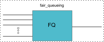
Fair Queueing (FQ): Uses round-robin approach to select the next packet to service. This method ensures that all the flows are serviced equally. Configure scheduler type as fair_queueing to create FQ scheduler.
-
Weighted Fair Queueing (WFQ): Uses a round-robin approach but with no guarantee of flow being serviced equally (like in FQ). The rotation of the next packet to service is based on the weight that is assigned to each flow. Configure scheduler type as weighted_fair_queueing to create WFQ scheduler.
-
Supported weight: 1 to 253
-
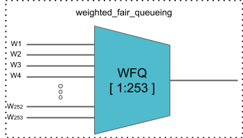
| In any WFQ scheduler, the lower the weight, the higher the bandwidth portion is awarded. |
-
Strict Priority (SP): Uses priority-based approach to service the flow. SP schedulers are supported in “hybrid” mode only. Hybrid mode combines FQ-WFQ schedulers using strict priority.
| The priority order for SP is: strict_priority_0 > strict_priority_1 > strict_priority_2 > strict_priority_3 (where strict_priority_0 being highest priority and strict_priority_3 being lowest) |
The following SP scheduler types are supported:
-
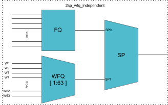
2 Strict Priority (2SP): Uses SP between 1-FQ and 1-WFQ. There are following types of 2SP hybrid schedulers:
-
type “2sp_wfq_independent”
-
Supported weight: 1 to 63
-
-
-
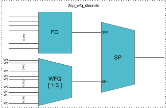
type “2sp_wfq_discrete”
-
Supported weight: { 1, 2, 3 }
-
-
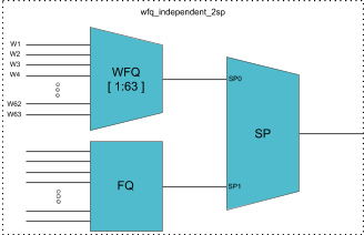
type “wfq_independent_2sp”
-
Supported weight: 1 to 63
-
-
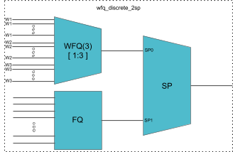
type “wfq_discrete_2sp”
-
Supported weight: { 1, 2, 3 }
-
-
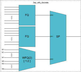
3 Strict Priority (3SP): maps 2-FQs and 1-WFQ
-
type: “3sp_wfq_discrete“
-
Supported weight: { 1, 2 }
-
-
-
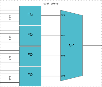
4 Strict Priority (4SP): maps 4-FQs using SP
-
type “strict_priority"
-
Scheduler-Map
Scheduler Map defines the set of relationships between parents and children in egress scheduling hierarchy. A child in a Scheduler Map configuration can be either Queue or Scheduler. A parent in a Scheduler Map configuration can be either a Port or Scheduler.
Connection Point and Weight
Child-queue or child-scheduler in a scheduler map configuration is connected to the parent-scheduler at “connection point (CP)“. Connection point configuration also has “weight” associated with it if the parent has a WFQ scheduler corresponding to that connection point. The valid connection point value for a child to connect to parent WFQ/FQ scheduler is no_priority and to connect to parent SP/Hybrid scheduler is between strict_priority_0 to strict_priority_3 (based on a number of Strict Priority points in parent scheduler).
Connection Types
There are five connection types in a scheduler map entry:
-
queue_to_port
-
queue_to_scheduler
-
scheduler_to_scheduler
-
scheduler_to_port
|
Shaper
Shaper is used to rate-limit the traffic at the egress. In RBFS, shapers can be attached to both Queue and Scheduler.
A shaper configuration defines the shaping rate in kilo-bits-per-seconds (kbps).
|
Low-rate Shaping
The Low-rate Shaping feature performs queueing and scheduler-level traffic shaping to rates lesser than 1000 Kbps so that the higher-priority (voice) traffic to flow at optimal levels.
| Low-rate Shaping is supported only on high-priority flows, that is high-flow configuration parameter. |
RBFS Access-Leaf and Consolidated-BNG platforms have been enabled with Low-rate Shaping by default. For information about the Low-rate Shaping feature enabled platforms, see section 'Feature/Resource Usage" in the Platform Guide.
RADIUS Controlled Dynamic Shapers
RBFS RADIUS services support dynamic shaper updates. The dynamic shaper when configured affects only the QoS instance of the corresponding subscriber but not other subscribers.
Profiles
A profile configuration defines the QoS profile that is attached to either a Subscriber interface or an L3 interface.
Profile maps the following QoS constructs to a Subscriber or an L3 interface:
-
Classifier
-
Multifield (MF) Classifier
-
Class Policer Map
-
Policer
-
Class Queue Map
-
Scheduler Map
-
Remark Map
Header Compensation
Queue Compensation
The rate at which the packets are dequeued from a queue depends on the credit received by that queue. The source of the credit received by a queue is the egress port to which the queue is mapped. When a packet is dequeued, the credit balance is decreased by the packet size. But, the packet size that is used must be adjusted to model the packet size at the egress, rather than its actual size at the ingress queue. Thus the header compensation is used to adjust for the differences in header size between ingress queue and egress port. RBFS supports static header compensation configuration per queue (in bytes).
Port Compensation
Similar to queue header compensation where header compensation is performed at the per-queue level, RBFS supports the following header compensation at the per-port level:
-
Ingress Header Compensation: In line with the header compensation option that we have per-queue, RBFS supports static header compensation configuration at the ingress to be used by the policing. Header compensation changes the effective size of the packet to compensate for changes in header size (such as the CRC removal) when considering the packet for policing. Unlike queue, RBFS ingress header compensation configuration is per ingress port (in bytes).
-
Egress Header Compensation: In line with the header compensation option that we have per-queue or per-port at the ingress, RBFS supports static header compensation configuration at the egress. The egress header compensation configuration is per egress port (in bytes).
| The supported range for header compensation is -64 to +64 bytes. |
L2TP QoS
The Layer 2 Tunneling Protocol (L2TP) QoS for upstream is similar to any other locally terminated subscriber. The QoS Profile is mapped dynamically via RADIUS for the L2TP subscribers.
The L2TP QoS for Downstream requires IPv4-TOS based BA Classifier which is mapped to L2TP Tunnel. The same can be achieved by attaching l2tp-classifier-name in global QoS configuration.
forwarding-options {
    class-of-service {
        global {
            l2tp-classifier-name l2tp-ip;
        }
    }
}
For Downstream queueing, there is no change. Queueing is applied using QoS Profile similar to locally terminated Subscribers.
The following features are supported for L2TP QoS.
-
Upstream
-
BA Classifier : IEEE 802.1p
-
Policing
-
Policer statistics
-
-
Remarking
-
|
-
Downstream
-
BA Classifier : IPv4-TOS
-
Queueing/Scheduling/Shaping
-
Queue statistics
-
-
Remark-Map : IEEE 802.1p (Class to VLAN priority remarking)
-
Guidelines
-
To avoid control traffic policing/shaping, the assumption is that the IEEE 802.1p bits in Upstream or IPv4-TOS bits in Downstream will be different for control and data traffic, control traffic is expected to have the highest precedence.
-
Upstream classification is based on IEEE 802.1p bits.
-
Downstream classification is based on IPv4-TOS bits of outer IP header.
-
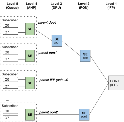
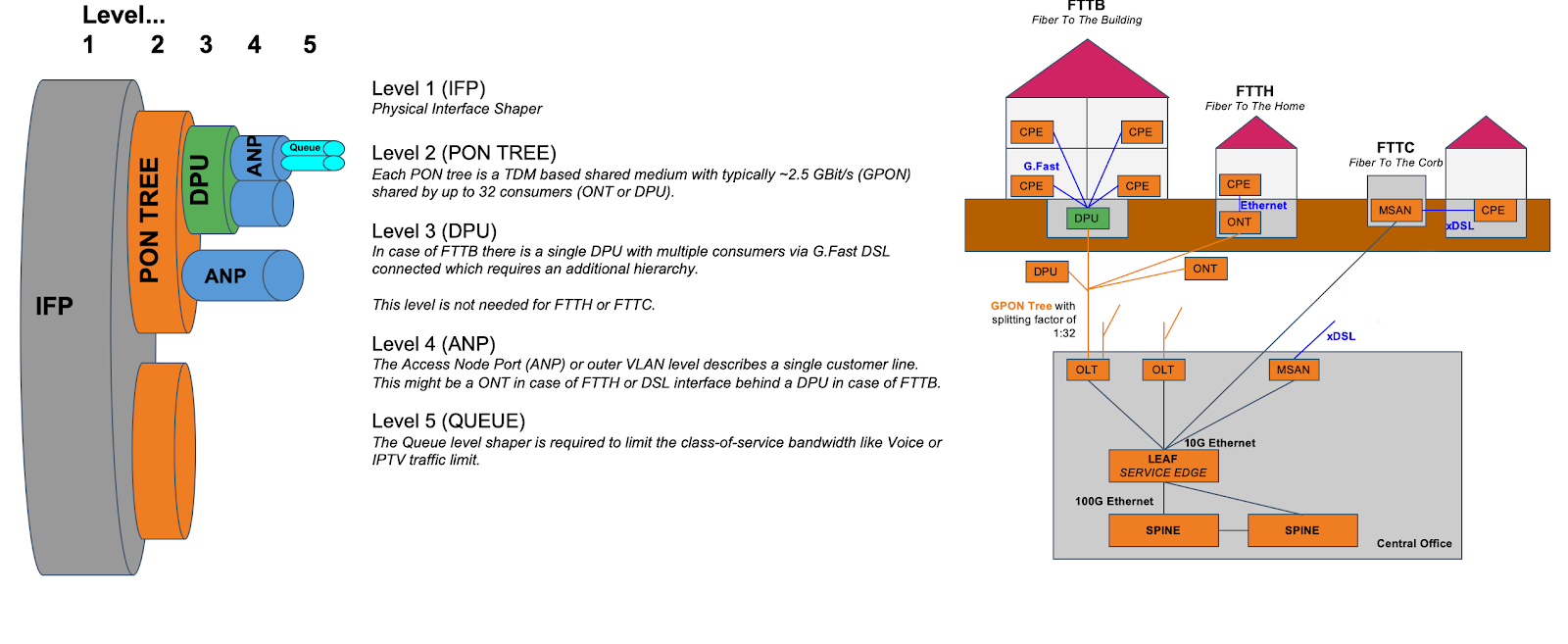
Multi-level H-QoS : Level-1 to Level-5
The following HQoS levels are required to build internet access services like FTTH, FTTC, or FTTB:
- Level-1 (IFP)
-
Physical Interface Shaper.
- Level-2 (PON TREE)
-
Each PON tree is a TDM based shared medium with typically ~2.5 GBit/s (GPON) shared by up to 32 consumers (ONT or DPU).
- Level-3 (DPU)
-
In case of FTTB there is a single DPU with multiple consumers via G.Fast DSL connected which requires an additional hierarchy. This level is not needed for FTTH or FTTC.
- Level-4 (ANP or Session)
-
The Access Node Port (ANP) or outer VLAN level describes a single customer line. This might be an ONT in case of FTTH or DSL interface behind a DPU in case of FTTB. This level can be also represented on PPPoE sessions as long as just one session is permitted per VLAN.
- Level-5 (QUEUE)
-
The Queue level shaper is required to limit the class-of-service bandwidth like Voice or IPTV traffic limit.
The figure below shows the diagram along with QoS representing Level-1 to Level-5 Hierarchical scheduling.
The levels 4 and 5 are configured per logical interface (i.e. subscriber-ifl or l3-ifl). Separate scheduler-map representing levels 1 to 3 connectivity shall be statically configured and mapped to the corresponding physical interface (IFP).
The child scheduler in a subscriber scheduler map is connected to the parent scheduler in a physical interface scheduler map using the following way:
-
Dynamically via RADIUS in case of dynamic subscribers like PPPoE sessions (Subscriber-IFL).
The figure below shows the same details as the preceding figure before with the different levels but from the DPU-PON-IFP scheduler-map point of view.