1. RBFS C-BNG with Redundancy for IPoE Subscribers
1.1. Overview
RtBrick provides reference design architectures designed and validated with in-house testing tools and methods. This document guides you to validate RBFS Consolidated BNG - IPoE with Redundancy implementation.
1.2. About RBFS Redundancy
RBFS Redundancy protects subscriber services from node and link outages. It provides mechanisms to enhance network resiliency that enables subscriber workloads to remain functional by ensuring a reliable switchover in the event of a node or link outage. With RBFS Redundancy, if one node/protected link goes down, another node can automatically take over the services for a subscriber group.
RBFS Redundancy protects subscriber groups using an active-standby node cluster model. The active node for a subscriber group runs the workload, and the peer node, which acts as standby, mirrors the subscriber state data from the peer (active) and takes over the workload in the event of a node or link failure. It ensures that traffic can keep flowing in the event of an outage. For more information about RBFS redundancy solution, see RBFS Redundancy Solution Guide.
1.3. About this Guide
It is recommended that you read this document after reading the RBFS C-BNG for IPoE Subscribers Reference Design Guide, which provides all required configuration information and quick steps for validating the RBFS C-BNG with IPoE implementation. The configurations related to the protocols, Quality of Service (QoS), subscriber management, and FreeRADIUS Server are part of the RBFS C-BNG for IPoE Subscribers Reference Design Guide.
This document provides information about the RBFS C-BNG - IPoE deployment in Redundancy (high availability) mode. It is mandatory to complete all the required configurations described in the RBFS C-BNG for IPoE Subscribers Reference Design Guide before deploying the C-BNG in the redundancy mode.
The document presents a single use case scenario and provides information on validating this implementation. For more information on any specific application, refer to https://documents.rtbrick.com/.
Currently, the guide’s scope is limited to the basic features and configurations for validation purposes. This guide does not provide information about the advanced RBFS features such as multicast.
1.4. RBFS CBNG- IPoE with Redundancy Implementation Architecture
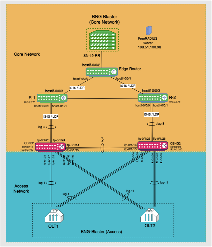
The architectural redundancy diagram below for RBFS C-BNG IPoE shows two bare metal switches installed with RBFS C-BNG software. This topology aims to demonstrate complete IPoE subscriber emulation with redundancy and routing to connect to the network uplink.
The devices are deployed in active and standby mode with respect to the lag bundles. cbng1 is configured as the active device for lag-1, and cbng2 is the standby device for lag-1. If one node goes down, the other node becomes stand-alone and takes over the subscribers for a subscriber group. RBFS devices (CBNGs) are connected to core routers on one side and OLTs (simulated by BNGBlaster) on the other.
When the active device goes down or a link failure occurs between the active RBFS device and the OLT device, the standby RBFS device detects the same and takes over from the previously active device.
In this topology:
-
SN-19-RR is the Service Node which is a Linux container running on an Ubuntu server. BNG Blaster, which emulates routing and access functions, runs on this container. This container also runs FreeRADIUS, which emulates RADIUS functions.
-
There are three routers; two acting as core routers (R-1 & R-2) and the third one as the Edge router. R-1, R-2, and Edge Router are RBFS virtual helper modes. The devices need not be RtBrick C-BNGs.
-
CBNG1 and CBNG2 are the DUTs, which are two bare metal switches installed with the RBFS C-BNG software. On one side, these are connected to the Access Network, while on the other side, they are connected to the Core Network.
-
The CBNGs form IS-IS adjacency and LDP session with the core routers R1 and R2, and the route reflectors (2 of them advertising 1M IPv4 prefixes each and the other two advertising 250K IPv6 prefixes each) are simulated by the BNG-Blaster.
-
The topology brings up 20K IPoE subscribers (2 OLTs with 10K subscribers each simulated by BNG Blaster) over a LAG interface. A failure of a CBNG does not affect a subscriber’s services since they are backed up among the CBNGs.
2. RBFS Redundancy Configurations
2.1. Configure RBFS Redundancy
To deploy RBFS in redundancy mode, you must complete the following configuration on both C-BNG nodes on top of the configuration explained in the RBFS C-BNG for IPoE Subscribers: Reference Design Guide.
-
Redundancy Profile
-
Redundancy Session
-
Link Aggregation Group for the Redundancy Session
-
Access for the Redundancy Session
The following steps provide the commands to configure RBFS Redundancy on both devices, which comprise the redundancy pair. For more detailed information about RBFS Redundancy Deployment, see RBFS Redundancy Solution Guide.
2.1.1. Redundancy Profile Configuration
Run the following commands to configure the redundancy profile on both devices (CBNG1 and CBNG2). Redundancy profile configuration is required to enable the devices to identify the peer in the network.
set redundancy profile rd_ipoe_olt1
set redundancy profile rd_ipoe_olt1 switchover-hold-timer 0
set redundancy profile rd_ipoe_olt1 peer ipv4 remote-address 192.0.2.200
set redundancy profile rd_ipoe_olt1 peer ipv4 update-source 192.0.2.100
set redundancy profile rd_ipoe_olt1 peer ipv4 instance default
set redundancy profile rd_ipoe_olt2
set redundancy profile rd_ipoe_olt2 switchover-hold-timer 0
set redundancy profile rd_ipoe_olt2 peer ipv4 remote-address 192.0.2.20
set redundancy profile rd_ipoe_olt2 peer ipv4 update-source 192.0.2.10
set redundancy profile rd_ipoe_olt2 peer ipv4 instance default
2.1.2. Redundancy Session Configuration
Run the following commands to configure the session for redundancy. Redundancy sessions can be uniquely identified by session IDs, which are used to store subscriber-specific data between active and standby devices.
set redundancy session 100
set redundancy session 100 priority 20
set redundancy session 100 profile rd_ipoe_olt1
set redundancy session 200
set redundancy session 200 priority 210
set redundancy session 200 profile rd_ipoe_olt2
Redundancy configuration from the node CBNG1 is shown below:
supervisor@rtbrick>cbng1.rtbrick.net: cfg> show config redundancy
{
  "rtbrick-config:redundancy": {
    "profile": [
      {
        "name": "rd_ipoe_olt1",
        "switchover-hold-timer": 0,
        "peer": {
          "ipv4": {
            "remote-address": "192.0.2.200",
            "update-source": "192.0.2.100",
            "instance": "default"
          }
        }
      },
      {
        "name": "rd_ipoe_olt2",
        "switchover-hold-timer": 0,
        "peer": {
          "ipv4": {
            "remote-address": "192.0.2.20",
            "update-source": "192.0.2.10",
            "instance": "default"
          }
        }
      }
    ],
    "session": [
      {
        "session-id": 100,
        "priority": 20,
        "profile": "rd_ipoe_olt1"
      },
      {
        "session-id": 200,
        "priority": 210,
        "profile": "rd_ipoe_olt2"
      }
    ]
  }
}
The redundancy configuration from the node CBNG2 is shown below:
supervisor@rtbrick>cbng2.rtbrick.net: cfg> show config redundancy
{
  "rtbrick-config:redundancy": {
    "profile": [
      {
        "name": "rd_ipoe_olt1",
        "switchover-hold-timer": 0,
        "peer": {
          "ipv4": {
            "remote-address": "192.0.2.100",
            "update-source": "192.0.2.200",
            "instance": "default"
          }
        }
      },
      {
        "name": "rd_ipoe_olt2",
        "switchover-hold-timer": 0,
        "peer": {
          "ipv4": {
            "remote-address": "192.0.2.10",
            "update-source": "192.0.2.20",
            "instance": "default"
          }
        }
      }
    ],
    "session": [
      {
        "session-id": 100,
        "priority": 10,
        "profile": "rd_ipoe_olt1"
      },
      {
        "session-id": 200,
        "priority": 220,
        "profile": "rd_ipoe_olt2"
      }
    ]
  }
}|
|
The session priority value determines the active/standby nodes for a session.
|
2.1.3. LAG Configuration for Redundancy
Run the following commands to configure LAG on both devices (CBNG1 and CBNG2) for redundancy. This configuration is required to associate the redundancy session with LAG.
Run the following commands to configure LAG on CBNG1 for redundancy.
set link-aggregation interface lag-1
set link-aggregation interface lag-1 mode lacp
set link-aggregation interface lag-1 minimum-link-count 3
set link-aggregation interface lag-1 redundancy-session-id 100
set link-aggregation interface lag-1 system-id a0:aa:aa:aa:aa:aa
set link-aggregation interface lag-1 member-interface ifp-0/1/26
set link-aggregation interface lag-1 member-interface ifp-0/1/27
set link-aggregation interface lag-1 member-interface ifp-0/1/28
set link-aggregation interface lag-11
set link-aggregation interface lag-11 mode lacp
set link-aggregation interface lag-11 minimum-link-count 3
set link-aggregation interface lag-11 redundancy-session-id 200
set link-aggregation interface lag-11 system-id a0:aa:aa:aa:aa:a0
set link-aggregation interface lag-11 member-interface ifp-0/1/31
set link-aggregation interface lag-11 member-interface ifp-0/1/33
set link-aggregation interface lag-11 member-interface ifp-0/1/35
set link-aggregation interface lag-2
set link-aggregation interface lag-2 mode lacp
set link-aggregation interface lag-2 minimum-link-count 1
set link-aggregation interface lag-2 member-interface ifp-0/1/14
set link-aggregation interface lag-2 member-interface ifp-0/1/15
set link-aggregation interface lag-3
set link-aggregation interface lag-3 mode lacp
set link-aggregation interface lag-3 minimum-link-count 1
set link-aggregation interface lag-3 member-interface ifp-0/1/23
set link-aggregation interface lag-3 member-interface ifp-0/1/24
LAG configuration for redundancy on CBNG1 is shown below:
supervisor@rtbrick>cbng1.rtbrick.net: cfg> show config link-aggregation
{
  "rtbrick-config:link-aggregation": {
    "interface": [
      {
        "interface-name": "lag-1",
        "mode": "lacp",
        "minimum-link-count": 3,
        "redundancy-session-id": 100,
        "system-id": "a0:aa:aa:aa:aa:aa",
        "member-interface": [
          {
            "member-interface-name": "ifp-0/1/26"
          },
          {
            "member-interface-name": "ifp-0/1/27"
          },
          {
            "member-interface-name": "ifp-0/1/28"
          }
        ]
      },
      {
        "interface-name": "lag-11",
        "mode": "lacp",
        "minimum-link-count": 3,
        "redundancy-session-id": 200,
        "system-id": "a0:aa:aa:aa:aa:a0",
        "member-interface": [
          {
            "member-interface-name": "ifp-0/1/31"
          },
          {
            "member-interface-name": "ifp-0/1/33"
          },
          {
            "member-interface-name": "ifp-0/1/35"
          }
        ]
      },
      {
        "interface-name": "lag-2",
        "mode": "lacp",
        "minimum-link-count": 1,
        "member-interface": [
          {
            "member-interface-name": "ifp-0/1/14"
          },
          {
            "member-interface-name": "ifp-0/1/15"
          }
        ]
      },
      {
        "interface-name": "lag-3",
        "mode": "lacp",
        "minimum-link-count": 1,
        "member-interface": [
          {
            "member-interface-name": "ifp-0/1/23"
          },
          {
            "member-interface-name": "ifp-0/1/24"
          }
        ]
      }
    ]
  }
}
Run the following commands to configure LAG on CBNG2 for redundancy.
set link-aggregation interface lag-1
set link-aggregation interface lag-1 mode lacp
set link-aggregation interface lag-1 minimum-link-count 3
set link-aggregation interface lag-1 redundancy-session-id 100
set link-aggregation interface lag-1 system-id a0:aa:aa:aa:aa:aa
set link-aggregation interface lag-1 member-interface ifp-0/1/26
set link-aggregation interface lag-1 member-interface ifp-0/1/27
set link-aggregation interface lag-1 member-interface ifp-0/1/28
set link-aggregation interface lag-11
set link-aggregation interface lag-11 mode lacp
set link-aggregation interface lag-11 minimum-link-count 3
set link-aggregation interface lag-11 redundancy-session-id 200
set link-aggregation interface lag-11 system-id a0:aa:aa:aa:aa:a0
set link-aggregation interface lag-11 member-interface ifp-0/1/31
set link-aggregation interface lag-11 member-interface ifp-0/1/33
set link-aggregation interface lag-11 member-interface ifp-0/1/35
set link-aggregation interface lag-2
set link-aggregation interface lag-2 mode lacp
set link-aggregation interface lag-2 minimum-link-count 1
set link-aggregation interface lag-2 member-interface ifp-0/1/14
set link-aggregation interface lag-2 member-interface ifp-0/1/15
set link-aggregation interface lag-3
set link-aggregation interface lag-3 mode lacp
set link-aggregation interface lag-3 minimum-link-count 1
set link-aggregation interface lag-3 member-interface ifp-0/1/23
set link-aggregation interface lag-3 member-interface ifp-0/1/24
LAG configuration for redundancy on CBNG2 is shown below:
supervisor@rtbrick>cbng2.rtbrick.net: cfg> show config link-aggregation
{
  "rtbrick-config:link-aggregation": {
    "interface": [
      {
        "interface-name": "lag-1",
        "mode": "lacp",
        "minimum-link-count": 3,
        "redundancy-session-id": 100,
        "system-id": "a0:aa:aa:aa:aa:aa",
        "member-interface": [
          {
            "member-interface-name": "ifp-0/1/30"
          },
          {
            "member-interface-name": "ifp-0/1/32"
          },
          {
            "member-interface-name": "ifp-0/1/33"
          }
        ]
      },
      {
        "interface-name": "lag-11",
        "mode": "lacp",
        "minimum-link-count": 3,
        "redundancy-session-id": 200,
        "system-id": "a0:aa:aa:aa:aa:a0",
        "member-interface": [
          {
            "member-interface-name": "ifp-0/1/34"
          },
          {
            "member-interface-name": "ifp-0/1/35"
          },
          {
            "member-interface-name": "ifp-0/1/47"
          }
        ]
      },
      {
        "interface-name": "lag-2",
        "mode": "lacp",
        "minimum-link-count": 1,
        "member-interface": [
          {
            "member-interface-name": "ifp-0/1/14"
          },
          {
            "member-interface-name": "ifp-0/1/15"
          }
        ]
      },
      {
        "interface-name": "lag-3",
        "mode": "lacp",
        "minimum-link-count": 1,
        "member-interface": [
          {
            "member-interface-name": "ifp-0/1/25"
          },
          {
            "member-interface-name": "ifp-0/1/26"
          }
        ]
      }
    ]
  }
}
2.1.4. Access Configuration for Redundancy
Run the following commands to configure access interfaces on both of the devices (CBNG1 and CBNG2) for enabling redundancy.
set access chassis-id 1
set access aaa-profile ipoe-aaa
set access aaa-profile ipoe-aaa session-timeout 0
set access aaa-profile ipoe-aaa idle-timeout 0
set access aaa-profile ipoe-aaa aaa-radius-profile aaa-radius1
set access aaa-profile ipoe-aaa authentication order RADIUS
set access aaa-profile ipoe-aaa accounting order RADIUS
set access aaa-profile ipoe-aaa accounting interim-interval 30
set access aaa-profile ipoe-aaa accounting session-id-format DEFAULT
set access radius-profile aaa-radius1
set access radius-profile aaa-radius1 nas-identifier 192.0.2.1
set access radius-profile aaa-radius1 nas-port-type Ethernet
set access radius-profile aaa-radius1 authentication radius-server-profile-name radius-srv1
set access radius-profile aaa-radius1 accounting radius-server-profile-name radius-srv1
set access radius-server radius-srv1
set access radius-server radius-srv1 address 198.51.100.98
set access radius-server radius-srv1 source-address 192.0.2.1
set access radius-server radius-srv1 secret-encrypted-text $2b2feb12f730107454b1be6a0f8242b0f
set access radius-server radius-srv1 routing-instance default
set access radius-server radius-srv1 authentication enable true
set access radius-server radius-srv1 authentication timeout 10
set access radius-server radius-srv1 accounting enable true
set access radius-server radius-srv1 accounting timeout 10
set access radius-server radius-srv1 coa enable true
set access access-profile ipoe
set access access-profile ipoe protocol dhcp enable true
set access access-profile ipoe protocol dhcp lease-time 3600
set access access-profile ipoe protocol dhcpv6 enable true
set access access-profile ipoe protocol dhcpv6 lifetime 3600
set access access-profile ipoe address-family ipv4 enable true
set access access-profile ipoe address-family ipv4 pool-name pool1
set access access-profile ipoe address-family ipv4 instance default
set access access-profile ipoe address-family ipv6 enable true
set access access-profile ipoe address-family ipv6 pool-name pool1
set access access-profile ipoe address-family ipv6 prefix-delegation-pool-name pool2
set access access-profile ipoe address-family ipv6 instance default
set access interface double-tagged lag-1 1001 2000 1001 1100
set access interface double-tagged lag-1 1001 2000 1001 1100 access-type IPoE
set access interface double-tagged lag-1 1001 2000 1001 1100 access-profile-name ipoe
set access interface double-tagged lag-1 1001 2000 1001 1100 aaa-profile-name ipoe-aaa
set access interface double-tagged lag-1 1001 2000 1001 1100 gateway-ifl lo-0/0/0/10
set access interface double-tagged lag-1 1001 2000 1001 1100 redundancy-session-id 100
set access interface double-tagged lag-11 2001 3000 1001 1100
set access interface double-tagged lag-11 2001 3000 1001 1100 access-type IPoE
set access interface double-tagged lag-11 2001 3000 1001 1100 access-profile-name ipoe
set access interface double-tagged lag-11 2001 3000 1001 1100 aaa-profile-name ipoe-aaa
set access interface double-tagged lag-11 2001 3000 1001 1100 gateway-ifl lo-0/0/0/10
set access interface double-tagged lag-11 2001 3000 1001 1100 redundancy-session-id 200
set access pool pool1
set access pool pool1 ipv4-address low 11.100.128.1
set access pool pool1 ipv4-address high 15.100.128.255
set access pool pool1 ipv6-prefix low fc55:100:1:1::1/128
set access pool pool1 ipv6-prefix high fc55:100:1:2::5555/128
set access pool pool2
set access pool pool2 ipv6-prefix low fc56:100:1::/56
set access pool pool2 ipv6-prefix high fc56:100:5000::/56set redundancy profile rd_ipoe_olt1
Access Configuration for Redundancy on CBNG-1 is shown below:
supervisor@rtbrick>cbng1.rtbrick.net: cfg> show config access
{
  "rtbrick-config:access": {
    "chassis-id": 1,
    "aaa-profile": [
      {
        "profile-name": "ipoe-aaa",
        "session-timeout": 0,
        "idle-timeout": 0,
        "aaa-radius-profile": "aaa-radius1",
        "authentication": {
          "order": "RADIUS"
        },
        "accounting": {
          "order": "RADIUS",
          "interim-interval": 30,
          "session-id-format": "DEFAULT"
        }
      }
    ],
    "radius-profile": [
      {
        "profile-name": "aaa-radius1",
        "nas-identifier": "192.0.2.1",
        "nas-port-type": "Ethernet",
        "authentication": {
          "radius-server-profile-name": [
            "radius-srv1"
            ]
        },
        "accounting": {
          "radius-server-profile-name": [
            "radius-srv1"
            ]
        }
      }
    ],
    "radius-server": [
      {
        "server-name": "radius-srv1",
        "address": "198.51.100.98",
        "source-address": "192.0.2.1",
        "secret-encrypted-text": "$2b2feb12f730107454b1be6a0f8242b0f",
        "routing-instance": "default",
        "authentication": {
          "enable": "true",
          "timeout": 10
        },
        "accounting": {
          "enable": "true",
          "timeout": 10
        },
        "coa": {
          "enable": "true"
        }
      }
    ],
    "access-profile": [
      {
        "profile-name": "ipoe",
        "protocol": {
          "dhcp": {
            "enable": "true",
            "lease-time": 3600
          },
          "dhcpv6": {
            "enable": "true",
            "lifetime": 3600
          }
        },
        "address-family": {
          "ipv4": {
            "enable": "true",
            "pool-name": "pool1",
            "instance": "default"
          },
          "ipv6": {
            "enable": "true",
            "pool-name": "pool1",
            "prefix-delegation-pool-name": "pool2",
            "instance": "default"
          }
        }
      }
    ],
    "interface": {
      "double-tagged": [
        {
          "interface-name": "lag-1",
          "outer-vlan-min": 1001,
          "outer-vlan-max": 2000,
          "inner-vlan-min": 1001,
          "inner-vlan-max": 1100,
          "access-type": "IPoE",
          "access-profile-name": "ipoe",
          "aaa-profile-name": "ipoe-aaa",
          "gateway-ifl": "lo-0/0/0/10",
          "redundancy-session-id": 100
        },
        {
          "interface-name": "lag-11",
          "outer-vlan-min": 2001,
          "outer-vlan-max": 3000,
          "inner-vlan-min": 1001,
          "inner-vlan-max": 1100,
          "access-type": "IPoE",
          "access-profile-name": "ipoe",
          "aaa-profile-name": "ipoe-aaa",
          "gateway-ifl": "lo-0/0/0/10",
          "redundancy-session-id": 200
        }
      ]
    },
    "pool": [
      {
        "pool-name": "pool1",
        "ipv4-address": {
          "low": "11.100.128.1",
          "high": "15.100.128.255"
        },
        "ipv6-prefix": {
          "low": "fc55:100:1:1::1/128",
          "high": "fc55:100:1:2::5555/128"
        }
      },
      {
        "pool-name": "pool2",
        "ipv6-prefix": {
          "low": "fc56:100:1::/56",
          "high": "fc56:100:5000::/56"
        }
      }
    ]
  }
}
Access Configuration for Redundancy on CBNG-2 is shown below:
supervisor@rtbrick>cbng2.rtbrick.net: cfg> show config access
{
  "rtbrick-config:access": {
    "chassis-id": 2,
    "aaa-profile": [
      {
        "profile-name": "ipoe-aaa",
        "session-timeout": 0,
        "idle-timeout": 0,
        "aaa-radius-profile": "aaa-radius1",
        "authentication": {
          "order": "RADIUS"
        },
        "accounting": {
          "order": "RADIUS",
          "interim-interval": 30,
          "session-id-format": "DEFAULT"
        }
      }
    ],
    "radius-profile": [
      {
        "profile-name": "aaa-radius1",
        "nas-identifier": "192.0.2.2",
        "nas-port-type": "Ethernet",
        "authentication": {
          "radius-server-profile-name": [
            "radius-srv1"
            ]
        },
        "accounting": {
          "radius-server-profile-name": [
            "radius-srv1"
            ]
        }
      }
    ],
    "radius-server": [
      {
        "server-name": "radius-srv1",
        "address": "198.51.100.98",
        "source-address": "192.0.2.2",
        "secret-encrypted-text": "$2b2feb12f730107454b1be6a0f8242b0f",
        "routing-instance": "default",
        "authentication": {
          "enable": "true",
          "timeout": 10
        },
        "accounting": {
          "enable": "true",
          "timeout": 10
        },
        "coa": {
          "enable": "true"
        }
      }
    ],
    "access-profile": [
      {
        "profile-name": "ipoe",
        "protocol": {
          "dhcp": {
            "enable": "true",
            "lease-time": 3600
          },
          "dhcpv6": {
            "enable": "true",
            "lifetime": 3600
          }
        },
        "address-family": {
          "ipv4": {
            "enable": "true",
            "pool-name": "pool1",
            "instance": "default"
          },
          "ipv6": {
            "enable": "true",
            "pool-name": "pool1",
            "prefix-delegation-pool-name": "pool2",
            "instance": "default"
          }
        }
      }
    ],
    "interface": {
      "double-tagged": [
        {
          "interface-name": "lag-1",
          "outer-vlan-min": 1001,
          "outer-vlan-max": 2000,
          "inner-vlan-min": 1001,
          "inner-vlan-max": 1100,
          "access-type": "IPoE",
          "access-profile-name": "ipoe",
          "aaa-profile-name": "ipoe-aaa",
          "gateway-ifl": "lo-0/0/0/10",
          "redundancy-session-id": 100
        },
        {
          "interface-name": "lag-11",
          "outer-vlan-min": 2001,
          "outer-vlan-max": 3000,
          "inner-vlan-min": 1001,
          "inner-vlan-max": 1100,
          "access-type": "IPoE",
          "access-profile-name": "ipoe",
          "aaa-profile-name": "ipoe-aaa",
          "gateway-ifl": "lo-0/0/0/10",
          "redundancy-session-id": 200
        }
      ]
    },
    "pool": [
      {
        "pool-name": "pool1",
        "ipv4-address": {
          "low": "16.100.128.1",
          "high": "20.100.128.255"
        },
        "ipv6-prefix": {
          "low": "fc66:100:1:1::1/128",
          "high": "fc66:100:1:2::5555/128"
        }
      },
      {
        "pool-name": "pool2",
        "ipv6-prefix": {
          "low": "fc67:100:1::/56",
          "high": "fc67:100:5000::/56"
        }
      }
    ]
  }
}
supervisor@rtbrick>ufi09.q2c.u19.r4.nbg.rtbrick.net: cfg>
2.2. BNG Blaster Configuration
BNG Blaster is an open-source network testing platform for access and routing protocols. It can emulate massive PPPoE and IPoE (DHCP) subscribers, including IPTV, and L2TP (LNS). One can use this platform for end-to-end BNG and non-BNG router testing. For more information about BNG Blaster, see https://github.com/rtbrick/bngblaster
2.2.1. Configure LAG on BNG Blaster for Redundancy Validation
With BNG blaster, you can validate the C-BNG - IPoE with Redundancy solution implementation and the traffic streams. BNG Blaster uses the following configuration file to validate C-BNG - IPoE with Redundancy.
{
  "interfaces": {
    "tx-interval": 1,
    "rx-interval": 1,
    "lag": [
      {
        "interface": "lag1",
        "lacp": true,
        "lacp-timeout-short": true
      },
      {
        "interface": "lag11",
        "lacp": true,
        "lacp-timeout-short": true
      }
    ],
    "links": [
      {
        "interface": "SN-5-C1",
        "lag-interface": "lag1"
      },
      {
        "interface": "SN-6-C1",
        "lag-interface": "lag1"
      },
      {
        "interface": "SN-7-C1",
        "lag-interface": "lag1"
      },
      {
        "interface": "SN-11-C2",
        "lag-interface": "lag1"
      },
      {
        "interface": "SN-12-C2",
        "lag-interface": "lag1"
      },
      {
        "interface": "SN-13-C2",
        "lag-interface": "lag1"
      },
      {
        "interface": "SN-20-C1",
        "lag-interface": "lag11"
      },
      {
        "interface": "SN-21-C1",
        "lag-interface": "lag11"
      },
      {
        "interface": "SN-22-C1",
        "lag-interface": "lag11"
      },
      {
        "interface": "SN-23-C2",
        "lag-interface": "lag11"
      },
      {
        "interface": "SN-24-C2",
        "lag-interface": "lag11"
      },
      {
        "interface": "SN-25-C2",
        "lag-interface": "lag11"
      }
    ],
    "network": [
      {
        "interface": "SN-19-RR",
        "address": "192.0.2.130/30",
        "gateway": "192.0.2.129",
        "address-ipv6": "2001:db8::130",
        "gateway-ipv6": "2001:db8::129",
        "isis-instance-id": 1,
        "isis-level": 1,
        "ldp-instance-id": 1
      }
    ],
    "access": [
      {
        "interface": "lag1",
        "type": "ipoe",
        "agent-remote-id": "CBNG1.RTBRICK.{session-global}",
        "outer-vlan-min": 1001,
        "outer-vlan-max": 2000,
        "inner-vlan-min": 1001,
        "inner-vlan-max": 1100
      },
      {
        "interface": "lag11",
        "type": "ipoe",
        "agent-remote-id": "CBNG2.RTBRICK.{session-global}",
        "outer-vlan-min": 2001,
        "outer-vlan-max": 3000,
        "inner-vlan-min": 1001,
        "inner-vlan-max": 1100
      }
    ]
  },
  "sessions": {
    "count": 20000,
    "max-outstanding": 800,
    "start-rate": 400,
    "stop-rate": 400
  },
  "access-line": {
    "agent-remote-id": "DEU.RTBRICK.{session-global}",
    "agent-circuit-id": "0.0.0.0/0.0.0.0 eth 0:{session-global}",
    "rate-up": 2000,
    "rate-down": 16384,
    "dsl-type": 5
  },
  "dhcp": {
    "enable": true
  },
  "dhcpv6": {
    "ldra": true,
    "enable": true
  },
  "session-traffic": {
    "ipv4-pps": 1,
    "ipv6-pps": 1,
    "ipv6pd-pps": 1,
    "autostart": false
  },
  "ldp": [
    {
      "instance-id": 1,
      "lsr-id": "192.0.2.6",
      "keepalive-time": 30,
      "raw-update-file": "/home/supervisor/ldp_1000.ldp"
    }
  ],
  "isis": [
    {
      "instance-id": 1,
      "area": [
        "49.0002/24"
      ],
      "system-id": "0204.0000.0001",
      "router-id": "192.0.2.6",
      "hostname": "BBL-RR",
      "hello-padding": true,
      "teardown-time": 30,
      "external": {
        "mrt-file": "/home/supervisor/isis_1000.mrt",
        "connections": [
          {
            "system-id": "0300.1001.0001",
            "l1-metric": 10
          }
        ]
      }
    }
  ],
  "bgp": [
    {
      "__comment__": "RR1-C1-IPv4",
      "network-interface": "SN-19-RR",
      "local-ipv4-address": "198.51.100.10",
      "peer-ipv4-address": "192.0.2.1",
      "raw-update-file": "/home/supervisor/ipv4_nlri_nh1.bgp",
      "local-as": 4200000001,
      "peer-as": 4200000001
    },
    {
      "__comment__": "RR1-C1-IPv6",
      "network-interface": "SN-19-RR",
      "local-ipv4-address": "198.51.100.20",
      "peer-ipv4-address": "192.0.2.1",
      "raw-update-file": "/home/supervisor/ipv6_nlri_nh1.bgp",
      "local-as": 4200000001,
      "peer-as": 4200000001
    },
    {
      "__comment__": "RR1-C2-IPv4",
      "network-interface": "SN-19-RR",
      "local-ipv4-address": "198.51.100.10",
      "peer-ipv4-address": "192.0.2.2",
      "raw-update-file": "/home/supervisor/ipv4_nlri_nh1.bgp",
      "local-as": 4200000001,
      "peer-as": 4200000001
    },
    {
      "__comment__": "RR1-C2-IPv6",
      "network-interface": "SN-19-RR",
      "local-ipv4-address": "198.51.100.20",
      "peer-ipv4-address": "192.0.2.2",
      "raw-update-file": "/home/supervisor/ipv6_nlri_nh1.bgp",
      "local-as": 4200000001,
      "peer-as": 4200000001
    },
    {
      "__comment__": "RR2-C1-IPv4",
      "network-interface": "SN-19-RR",
      "local-ipv4-address": "198.51.100.30",
      "peer-ipv4-address": "192.0.2.1",
      "raw-update-file": "/home/supervisor/ipv4_nlri_nh2.bgp",
      "local-as": 4200000001,
      "peer-as": 4200000001
    },
    {
      "__comment__": "RR2-C1-IPv6",
      "network-interface": "SN-19-RR",
      "local-ipv4-address": "198.51.100.40",
      "peer-ipv4-address": "192.0.2.1",
      "raw-update-file": "/home/supervisor/ipv6_nlri_nh2.bgp",
      "local-as": 4200000001,
      "peer-as": 4200000001
    },
    {
      "__comment__": "RR2-C2-IPv4",
      "network-interface": "SN-19-RR",
      "local-ipv4-address": "198.51.100.30",
      "peer-ipv4-address": "192.0.2.2",
      "raw-update-file": "/home/supervisor/ipv4_nlri_nh2.bgp",
      "local-as": 4200000001,
      "peer-as": 4200000001
    },
    {
      "__comment__": "RR2-C2-IPv6",
      "network-interface": "SN-19-RR",
      "local-ipv4-address": "198.51.100.40",
      "peer-ipv4-address": "192.0.2.2",
      "raw-update-file": "/home/supervisor/ipv6_nlri_nh2.bgp",
      "local-as": 4200000001,
      "peer-as": 4200000001
    }
  ]
}
2.3. Validating C-BNG Redundancy and Reachability
The following command line string shows how to start a BNG Blaster instance:
sudo bngblaster -C <filename> -I -c102.3.1. Redundancy Session Data and Subscriber States on Active and Standby Nodes
CBNG-1: Before switchover, which is the actual state
supervisor@rtbrick>cbng1.rtbrick.net: op> show redundancy session
Instance: default
  Session ID     Interface      Peer           Source         State          Peer state     Keepalive rcvd      Keepalive sent
  100            lag-1          192.0.2.200    192.0.2.100    active         standby        91                  92
  200            lag-11         192.0.2.20     192.0.2.10     standby        active         91                  91
supervisor@rtbrick>cbng1.rtbrick.net: op>
supervisor@rtbrick>cbng1.rtbrick.net: op> show subscriber
Subscriber-Id Interface VLAN Type State
1369375761697341441 lag-1 1001:1001 IPoE ESTABLISHED
1369375761697341442 lag-1 1001:1002 IPoE ESTABLISHED
1369375761697341443 lag-1 1001:1003 IPoE ESTABLISHED
1369375761697341444 lag-1 1001:1004 IPoE ESTABLISHED
1369375761697341445 lag-1 1001:1005 IPoE ESTABLISHED
2522297266304188417 lag-11 2001:1001 IPoE STANDBY
2522297266304188418 lag-11 2001:1002 IPoE STANDBY
2522297266304188419 lag-11 2001:1003 IPoE STANDBY
2522297266304188420 lag-11 2001:1004 IPoE STANDBY
2522297266304188421 lag-11 2001:1005 IPoE STANDBY
supervisor@rtbrick>cbng1.rtbrick.net: op>CBNG-2: Before switchover, which is the actual state
supervisor@rtbrick>cbng2.rtbrick.net: op>  show redundancy session
Instance: default
  Session ID     Interface      Peer           Source         State          Peer state     Keepalive rcvd      Keepalive sent
  100            lag-1          192.0.2.100    192.0.2.200    standby        active         94                  93
  200            lag-11         192.0.2.10     192.0.2.20     active         standby        93                  93
supervisor@rtbrick>cbng2.rtbrick.net: op>
supervisor@rtbrick>cbng2.rtbrick.net: op> show subscriber
Subscriber-Id Interface VLAN Type State
1369375761697341441 lag-1 1001:1001 IPoE STANDBY
1369375761697341442 lag-1 1001:1002 IPoE STANDBY
1369375761697341443 lag-1 1001:1003 IPoE STANDBY
1369375761697341444 lag-1 1001:1004 IPoE STANDBY
1369375761697341445 lag-1 1001:1005 IPoE STANDBY
2522297266304188417 lag-11 2001:1001 IPoE ESTABLISHED
2522297266304188418 lag-11 2001:1002 IPoE ESTABLISHED
2522297266304188419 lag-11 2001:1003 IPoE ESTABLISHED
2522297266304188420 lag-11 2001:1004 IPoE ESTABLISHED
2522297266304188421 lag-11 2001:1005 IPoE ESTABLISHED
supervisor@rtbrick>cbng2.rtbrick.net: op>2.3.2. Switchover Scenario for Link Failure Between Active C-BNG Node and Access (OLT) Node
After link (connecting OLT1 to CBNG1) is brought down, the state becomes down for the RD session 100 and for the same session, the other CBNG becomes stand-alone.
CBNG-1:
supervisor@rtbrick>cbng1.rtbrick.net: op> show redundancy session
Instance: default
  Session ID     Interface      Peer           Source         State          Peer state     Keepalive rcvd      Keepalive sent
  100            lag-1          192.0.2.200    192.0.2.100    down           stand-alone    113                 114
  200            lag-11         192.0.2.20     192.0.2.10     standby        active         114                 114
supervisor@rtbrick>cbng1.rtbrick.net: op>
supervisor@rtbrick>cbng1.rtbrick.net: op> show subscriber
Subscriber-Id Interface VLAN Type State
1369375761697341441 lag-1 1001:1001 IPoE STANDBY
1369375761697341442 lag-1 1001:1002 IPoE STANDBY
1369375761697341443 lag-1 1001:1003 IPoE STANDBY
1369375761697341444 lag-1 1001:1004 IPoE STANDBY
1369375761697341445 lag-1 1001:1005 IPoE STANDBY
2522297266304188417 lag-11 2001:1001 IPoE STANDBY
2522297266304188418 lag-11 2001:1002 IPoE STANDBY
2522297266304188419 lag-11 2001:1003 IPoE STANDBY
2522297266304188420 lag-11 2001:1004 IPoE STANDBY
2522297266304188421 lag-11 2001:1005 IPoE STANDBY
supervisor@rtbrick>cbng1.rtbrick.net: op>CBNG-2:
supervisor@rtbrick>cbng2.rtbrick.net: op> show redundancy session
Instance: default
  Session ID     Interface      Peer           Source         State          Peer state     Keepalive rcvd      Keepalive sent
  100            lag-1          192.0.2.100    192.0.2.200    stand-alone    down           115                 114
  200            lag-11         192.0.2.10     192.0.2.20     active         standby        115                 115
supervisor@rtbrick>cbng2.rtbrick.net: op>
supervisor@rtbrick>cbng2.rtbrick.net: op> show subscriber
Subscriber-Id Interface VLAN Type State
1369375761697341441 lag-1 1001:1001 IPoE ESTABLISHED
1369375761697341442 lag-1 1001:1002 IPoE ESTABLISHED
1369375761697341443 lag-1 1001:1003 IPoE ESTABLISHED
1369375761697341444 lag-1 1001:1004 IPoE ESTABLISHED
1369375761697341445 lag-1 1001:1005 IPoE ESTABLISHED
2522297266304188417 lag-11 2001:1001 IPoE ESTABLISHED
2522297266304188418 lag-11 2001:1002 IPoE ESTABLISHED
2522297266304188419 lag-11 2001:1003 IPoE ESTABLISHED
2522297266304188420 lag-11 2001:1004 IPoE ESTABLISHED
2522297266304188421 lag-11 2001:1005 IPoE ESTABLISHED
supervisor@rtbrick>cbng2.rtbrick.net: op>2.3.3. Failed OLT link comes up back (before node failure)
CBNG-1:
supervisor@rtbrick>cbng1.rtbrick.net: op> show redundancy session
Instance: default
  Session ID     Interface      Peer           Source         State          Peer state     Keepalive rcvd      Keepalive sent
  100            lag-1          192.0.2.200    192.0.2.100    standby        active         163                 164
  200            lag-11         192.0.2.20     192.0.2.10     standby        active         163                 163
supervisor@rtbrick>cbng1.rtbrick.net: op>
supervisor@rtbrick>cbng1.rtbrick.net: op> show subscriber
Subscriber-Id Interface VLAN Type State
1369375761697341441 lag-1 1001:1001 IPoE STANDBY
1369375761697341442 lag-1 1001:1002 IPoE STANDBY
1369375761697341443 lag-1 1001:1003 IPoE STANDBY
1369375761697341444 lag-1 1001:1004 IPoE STANDBY
1369375761697341445 lag-1 1001:1005 IPoE STANDBY
2522297266304188417 lag-11 2001:1001 IPoE STANDBY
2522297266304188418 lag-11 2001:1002 IPoE STANDBY
2522297266304188419 lag-11 2001:1003 IPoE STANDBY
2522297266304188420 lag-11 2001:1004 IPoE STANDBY
2522297266304188421 lag-11 2001:1005 IPoE STANDBY
supervisor@rtbrick>cbng1.rtbrick.net: op>CBNG-2:
supervisor@rtbrick>cbng2.rtbrick.net: op> show redundancy session
Instance: default
  Session ID     Interface      Peer           Source         State          Peer state     Keepalive rcvd      Keepalive sent
  100            lag-1          192.0.2.100    192.0.2.200    active         standby        166                 165
  200            lag-11         192.0.2.10     192.0.2.20     active         standby        165                 165
supervisor@rtbrick>cbng2.rtbrick.net: op>
supervisor@rtbrick>cbng2.rtbrick.net: op> show subscriber
Subscriber-Id Interface VLAN Type State
1369375761697341441 lag-1 1001:1001 IPoE ESTABLISHED
1369375761697341442 lag-1 1001:1002 IPoE ESTABLISHED
1369375761697341443 lag-1 1001:1003 IPoE ESTABLISHED
1369375761697341444 lag-1 1001:1004 IPoE ESTABLISHED
1369375761697341445 lag-1 1001:1005 IPoE ESTABLISHED
2522297266304188417 lag-11 2001:1001 IPoE ESTABLISHED
2522297266304188418 lag-11 2001:1002 IPoE ESTABLISHED
2522297266304188419 lag-11 2001:1003 IPoE ESTABLISHED
2522297266304188420 lag-11 2001:1004 IPoE ESTABLISHED
2522297266304188421 lag-11 2001:1005 IPoE ESTABLISHED
supervisor@rtbrick>cbng2.rtbrick.net: op>|
|
To revert to the original active-standby mode based on the priority, a manual switchover can be performed using the switch-over session 100 confirm command.
|
2.3.4. Switchover Scenario for Active C-BNG Node Failure
CBNG-2’s Session State and Subscriber State After node failure
supervisor@rtbrick>cbng2.rtbrick.net: op> show redundancy session
Instance: default
  Session ID     Interface      Peer           Source         State          Peer state     Keepalive rcvd      Keepalive sent
  100            lag-1          192.0.2.100    192.0.2.200    stand-alone    invalid        194                 196
  200            lag-11         192.0.2.10     192.0.2.20     stand-alone    invalid        193                 196
supervisor@rtbrick>cbng2.rtbrick.net: op>
supervisor@rtbrick>cbng2.rtbrick.net: op> show subscriber
Subscriber-Id Interface VLAN Type State
1369375761697341441 lag-1 1001:1001 IPoE ESTABLISHED
1369375761697341442 lag-1 1001:1002 IPoE ESTABLISHED
1369375761697341443 lag-1 1001:1003 IPoE ESTABLISHED
1369375761697341444 lag-1 1001:1004 IPoE ESTABLISHED
1369375761697341445 lag-1 1001:1005 IPoE ESTABLISHED
2522297266304188417 lag-11 2001:1001 IPoE ESTABLISHED
2522297266304188418 lag-11 2001:1002 IPoE ESTABLISHED
2522297266304188419 lag-11 2001:1003 IPoE ESTABLISHED
2522297266304188420 lag-11 2001:1004 IPoE ESTABLISHED
2522297266304188421 lag-11 2001:1005 IPoE ESTABLISHED
supervisor@rtbrick>cbng2.rtbrick.net: op>2.4. Appendix A: CBNG1 Configuration
Show CBNG1 Configuration
{
"ietf-restconf:data": {
"rtbrick-config:system": {
"load-last-config": "true",
"host": {
"element-name": "ufi08.q2c.u23.r4.nbg.rtbrick.net",
"pod-name": "nbg4"
}
},
"rtbrick-config:redundancy": {
"profile": [
{
"name": "rd_ipoe_olt1",
"switchover-hold-timer": 0,
"peer": {
"ipv4": {
"remote-address": "192.0.2.200",
"update-source": "192.0.2.100",
"instance": "default"
}
}
},
{
"name": "rd_ipoe_olt2",
"switchover-hold-timer": 0,
"peer": {
"ipv4": {
"remote-address": "192.0.2.20",
"update-source": "192.0.2.10",
"instance": "default"
}
}
}
],
"session": [
{
"session-id": 100,
"priority": 20,
"profile": "rd_ipoe_olt1"
},
{
"session-id": 200,
"priority": 210,
"profile": "rd_ipoe_olt2"
}
]
},
"rtbrick-config:interface": [
{
"name": "ifp-0/1/23",
"speed": "10G"
},
{
"name": "ifp-0/1/24",
"speed": "10G"
},
{
"name": "ifp-0/1/25",
"speed": "10G"
},
{
"name": "ifp-0/1/26",
"speed": "10G"
},
{
"name": "ifp-0/1/27",
"speed": "10G"
},
{
"name": "ifp-0/1/28",
"speed": "10G"
},
{
"name": "ifp-0/1/31",
"speed": "10G"
},
{
"name": "ifp-0/1/33",
"speed": "10G"
},
{
"name": "ifp-0/1/35",
"speed": "10G"
},
{
"name": "ifp-0/1/37",
"speed": "10G"
},
{
"name": "ifp-0/1/40",
"speed": "10G"
},
{
"name": "ifp-0/1/41",
"speed": "10G"
},
{
"name": "ifp-0/1/42",
"speed": "10G"
},
{
"name": "ifp-0/1/43",
"speed": "10G"
},
{
"name": "lag-2",
"unit": [
{
"unit-id": 10,
"address": {
"ipv4": [
{
"prefix4": "192.0.2.61/30"
}
],
"ipv6": [
{
"prefix6": "2001:db8::61/127"
}
]
}
}
]
},
{
"name": "lag-3",
"unit": [
{
"unit-id": 10,
"address": {
"ipv4": [
{
"prefix4": "192.0.2.69/30"
}
],
"ipv6": [
{
"prefix6": "2001:db8::69/127"
}
]
}
}
]
},
{
"name": "lo-0/0/0",
"unit": [
{
"unit-id": 10,
"address": {
"ipv4": [
{
"prefix4": "192.0.2.1/32"
}
],
"ipv6": [
{
"prefix6": "2001:db8::1/128"
}
]
}
}
]
},
{
"name": "lo-0/0/1",
"unit": [
{
"unit-id": 10,
"address": {
"ipv4": [
{
"prefix4": "192.0.2.100/32"
}
],
"ipv6": [
{
"prefix6": "2001:db8::100/128"
}
]
}
}
]
},
{
"name": "lo-0/0/2",
"unit": [
{
"unit-id": 10,
"address": {
"ipv4": [
{
"prefix4": "192.0.2.10/32"
}
],
"ipv6": [
{
"prefix6": "2001:db8::10/128"
}
]
}
}
]
}
],
"rtbrick-config:forwarding-options": {
"class-of-service": {
"classifier": [
{
"classifier-name": "subs-exp-class",
"match-type": [
{
"match-type": "exp",
"codepoint": [
{
"codepoint": 1,
"class": "class-0"
},
{
"codepoint": 2,
"class": "class-1"
},
{
"codepoint": 3,
"class": "class-2"
},
{
"codepoint": 4,
"class": "class-3"
}
]
}
]
},
{
"classifier-name": "subs-pbit-class",
"match-type": [
{
"match-type": "ieee-802.1",
"codepoint": [
{
"codepoint": 1,
"class": "class-0"
},
{
"codepoint": 2,
"class": "class-1"
},
{
"codepoint": 3,
"class": "class-2"
},
{
"codepoint": 4,
"class": "class-3"
}
]
}
]
}
],
"class-policer-map": [
{
"class-policer-map-name": "policer-map-residential",
"class": [
{
"class": "class-0",
"policer-level": "level-1"
},
{
"class": "class-1",
"policer-level": "level-2"
},
{
"class": "class-2",
"policer-level": "level-3"
},
{
"class": "class-3",
"policer-level": "level-4"
}
]
}
],
"class-queue-map": [
{
"class-queue-map-name": "subs-4queues",
"class": [
{
"class-type": "class-0",
"queue-name": "BE_SUBS"
},
{
"class-type": "class-1",
"queue-name": "LD_SUBS"
},
{
"class-type": "class-2",
"queue-name": "LL_SUBS"
},
{
"class-type": "class-3",
"queue-name": "VO_SUBS"
}
]
}
],
"global": {
"multifield-classifier-name": "global_udpmfc"
},
"interface": [
{
"name": "lag-1",
"ingress-header-compensation": {
"bytes": 34,
"decrement": "true"
},
"scheduler-map-name": "schedmap-olt"
},
{
"name": "lag-11",
"ingress-header-compensation": {
"bytes": 34,
"decrement": "true"
},
"scheduler-map-name": "schedmap-olt"
}
],
"policer": [
{
"policer-name": "policer-residential",
"level1-rates": {
"cir": 2000,
"cbs": 1000,
"pir": 2500,
"pbs": 1000
},
"level2-rates": {
"cir": 3000,
"cbs": 1000,
"pir": 3500,
"pbs": 1000
},
"level3-rates": {
"cir": 4000,
"cbs": 1000,
"pir": 4500,
"pbs": 1000
},
"level4-rates": {
"cir": 1000,
"cbs": 1000,
"pir": 1500,
"pbs": 1000
},
"levels": 4,
"type": "two-rate-three-color"
},
{
"policer-name": "policer-residential-gold",
"level1-rates": {
"cir": 1000,
"cbs": 1000,
"pir": 1500,
"pbs": 1000
},
"level2-rates": {
"cir": 2000,
"cbs": 1000,
"pir": 2500,
"pbs": 1000
},
"level3-rates": {
"cir": 3000,
"cbs": 1000,
"pir": 3500,
"pbs": 1000
},
"level4-rates": {
"cir": 1000,
"cbs": 1000,
"pir": 1500,
"pbs": 1000
},
"levels": 4,
"type": "two-rate-three-color"
},
{
"policer-name": "policer-residential-platinum",
"level1-rates": {
"cir": 5000,
"cbs": 1000,
"pir": 5500,
"pbs": 1000
},
"level2-rates": {
"cir": 6000,
"cbs": 1000,
"pir": 6500,
"pbs": 1000
},
"level3-rates": {
"cir": 5000,
"cbs": 1000,
"pir": 5500,
"pbs": 1000
},
"level4-rates": {
"cir": 6000,
"cbs": 1000,
"pir": 6500,
"pbs": 1000
},
"levels": 4,
"type": "two-rate-three-color"
}
],
"profile": [
{
"profile-name": "subs-triple-play",
"classifier-name": "subs-pbit-class",
"class-queue-map-name": "subs-4queues",
"remark-map-name": "subs-remarking-triple-play",
"class-policer-map-name": "policer-map-residential",
"policer-name": "policer-residential",
"scheduler-map-name": "subs-4queues-triple-play"
},
{
"profile-name": "subs-triple-play-gold",
"classifier-name": "subs-pbit-class",
"class-queue-map-name": "subs-4queues",
"remark-map-name": "subs-remarking-triple-play",
"class-policer-map-name": "policer-map-residential",
"policer-name": "policer-residential-gold",
"scheduler-map-name": "subs-4queues-triple-play-gold"
},
{
"profile-name": "subs-triple-play-platinum",
"classifier-name": "subs-pbit-class",
"class-queue-map-name": "subs-4queues",
"remark-map-name": "subs-remarking-triple-play",
"class-policer-map-name": "policer-map-residential",
"policer-name": "policer-residential-platinum",
"scheduler-map-name": "subs-4queues-triple-play-platinum"
}
],
"queue": [
{
"queue-name": "BE_SUBS",
"queue-size": 375000,
"header-compensation": {
"bytes": 22,
"decrement": "true"
}
},
{
"queue-name": "LD_SUBS",
"queue-size": 625000,
"header-compensation": {
"bytes": 22,
"decrement": "true"
}
},
{
"queue-name": "LL_SUBS",
"queue-size": 625000,
"header-compensation": {
"bytes": 22,
"decrement": "true"
}
},
{
"queue-name": "VO_SUBS",
"queue-size": 156250,
"shaper-name": "shaper_VO",
"header-compensation": {
"bytes": 22,
"decrement": "true"
}
}
],
"queue-group": [
{
"queue-group-name": "subs-4queues",
"queue-numbers": 4
}
],
"remark-map": [
{
"remark-map-name": "subs-remarking-triple-play",
"remark-type": [
{
"remark-type": "ieee-802.1",
"match-codepoint": [
{
"match-codepoint": 1,
"color": [
{
"color": "all",
"remark-codepoint": 3
}
]
},
{
"match-codepoint": 2,
"color": [
{
"color": "all",
"remark-codepoint": 4
}
]
},
{
"match-codepoint": 3,
"color": [
{
"color": "all",
"remark-codepoint": 5
}
]
},
{
"match-codepoint": 224,
"color": [
{
"color": "all",
"remark-codepoint": 6
}
]
}
]
}
]
}
],
"scheduler": [
{
"scheduler-name": "pon0",
"shaper-name": "pon_shaper",
"type": "fair_queueing"
},
{
"scheduler-name": "pon1",
"type": "fair_queueing"
},
{
"scheduler-name": "subs-4queues",
"shaper-name": "shaper_session",
"type": "strict_priority",
"composite": "false"
},
{
"scheduler-name": "subs-4queues-gold",
"shaper-name": "shaper_session_gold",
"type": "strict_priority",
"composite": "false"
},
{
"scheduler-name": "subs-4queues-platinum",
"shaper-name": "shaper_session_platinum",
"type": "strict_priority",
"composite": "false"
}
],
"scheduler-map": [
{
"scheduler-map-name": "schedmap-olt",
"scheduler-name": [
{
"name": "pon0",
"port-connection": "scheduler_to_port"
},
{
"name": "pon1",
"port-connection": "scheduler_to_port"
}
]
},
{
"scheduler-map-name": "subs-4queues-triple-play",
"queue-group-name": [
{
"group-name": "subs-4queues",
"queue-name": [
{
"name": "BE_SUBS",
"parent-flow": "low-flow",
"parent-scheduler-name": "subs-4queues",
"connection-point": "strict_priority_3"
},
{
"name": "LD_SUBS",
"parent-flow": "high-flow",
"parent-scheduler-name": "subs-4queues",
"connection-point": "strict_priority_1"
},
{
"name": "LL_SUBS",
"parent-flow": "high-flow",
"parent-scheduler-name": "subs-4queues",
"connection-point": "strict_priority_2"
},
{
"name": "VO_SUBS",
"parent-flow": "high-flow",
"parent-scheduler-name": "subs-4queues",
"connection-point": "strict_priority_0"
}
]
}
],
"scheduler-name": [
{
"name": "subs-4queues",
"port-connection": "scheduler_to_port"
}
]
},
{
"scheduler-map-name": "subs-4queues-triple-play-gold",
"queue-group-name": [
{
"group-name": "subs-4queues",
"queue-name": [
{
"name": "BE_SUBS",
"parent-flow": "low-flow",
"parent-scheduler-name": "subs-4queues-gold",
"connection-point": "strict_priority_3"
},
{
"name": "LD_SUBS",
"parent-flow": "high-flow",
"parent-scheduler-name": "subs-4queues-gold",
"connection-point": "strict_priority_1"
},
{
"name": "LL_SUBS",
"parent-flow": "high-flow",
"parent-scheduler-name": "subs-4queues-gold",
"connection-point": "strict_priority_2"
},
{
"name": "VO_SUBS",
"parent-flow": "high-flow",
"parent-scheduler-name": "subs-4queues-gold",
"connection-point": "strict_priority_0"
}
]
}
],
"scheduler-name": [
{
"name": "subs-4queues-gold",
"port-connection": "scheduler_to_port"
}
]
},
{
"scheduler-map-name": "subs-4queues-triple-play-platinum",
"queue-group-name": [
{
"group-name": "subs-4queues",
"queue-name": [
{
"name": "BE_SUBS",
"parent-flow": "low-flow",
"parent-scheduler-name": "subs-4queues-platinum",
"connection-point": "strict_priority_3"
},
{
"name": "LD_SUBS",
"parent-flow": "high-flow",
"parent-scheduler-name": "subs-4queues-platinum",
"connection-point": "strict_priority_1"
},
{
"name": "LL_SUBS",
"parent-flow": "high-flow",
"parent-scheduler-name": "subs-4queues-platinum",
"connection-point": "strict_priority_2"
},
{
"name": "VO_SUBS",
"parent-flow": "high-flow",
"parent-scheduler-name": "subs-4queues-platinum",
"connection-point": "strict_priority_0"
}
]
}
],
"scheduler-name": [
{
"name": "subs-4queues-platinum",
"port-connection": "scheduler_to_port"
}
]
}
],
"shaper": [
{
"shaper-name": "pon_shaper",
"shaping-rate-high": 1000000,
"shaping-rate-low": 1000000
},
{
"shaper-name": "shaper_VO",
"shaping-rate-high": 1000,
"shaping-rate-low": 0
},
{
"shaper-name": "shaper_session",
"shaping-rate-high": 10000,
"shaping-rate-low": 2000
},
{
"shaper-name": "shaper_session_gold",
"shaping-rate-high": 13000,
"shaping-rate-low": 1000
},
{
"shaper-name": "shaper_session_platinum",
"shaping-rate-high": 15000,
"shaping-rate-low": 1000
}
],
"multifield-classifier": {
"acl": {
"l3v4": {
"rule": [
{
"rule-name": "global_mfc",
"ordinal": [
{
"ordinal-value": 101,
"match": {
"ipv4-tos": 128,
"source-ipv4-prefix": "192.0.2.132/32"
},
"action": {
"forward-class": "class-0"
}
},
{
"ordinal-value": 102,
"match": {
"ipv4-tos": 64,
"source-ipv4-prefix": "192.0.2.132/32"
},
"action": {
"forward-class": "class-1"
}
},
{
"ordinal-value": 103,
"match": {
"ipv4-tos": 96,
"source-ipv4-prefix": "192.0.2.132/32"
},
"action": {
"forward-class": "class-2"
}
},
{
"ordinal-value": 104,
"match": {
"ipv4-tos": 32,
"source-ipv4-prefix": "192.0.2.132/32"
},
"action": {
"forward-class": "class-3"
}
}
]
},
{
"rule-name": "global_udpmfc",
"ordinal": [
{
"ordinal-value": 101,
"match": {
"source-ipv4-prefix": "192.0.2.132/32",
"source-l4-port": 65001
},
"action": {
"forward-class": "class-0"
}
},
{
"ordinal-value": 102,
"match": {
"source-ipv4-prefix": "192.0.2.132/32",
"source-l4-port": 65002
},
"action": {
"forward-class": "class-1"
}
},
{
"ordinal-value": 103,
"match": {
"source-ipv4-prefix": "192.0.2.132/32",
"source-l4-port": 65003
},
"action": {
"forward-class": "class-2"
}
},
{
"ordinal-value": 104,
"match": {
"source-ipv4-prefix": "192.0.2.132/32",
"source-l4-port": 65004
},
"action": {
"forward-class": "class-3"
}
}
]
}
]
}
}
}
}
},
"rtbrick-config:link-aggregation": {
"interface": [
{
"interface-name": "lag-1",
"mode": "lacp",
"minimum-link-count": 3,
"redundancy-session-id": 100,
"system-id": "a0:aa:aa:aa:aa:aa",
"member-interface": [
{
"member-interface-name": "ifp-0/1/26"
},
{
"member-interface-name": "ifp-0/1/27"
},
{
"member-interface-name": "ifp-0/1/28"
}
]
},
{
"interface-name": "lag-11",
"mode": "lacp",
"minimum-link-count": 3,
"redundancy-session-id": 200,
"system-id": "a0:aa:aa:aa:aa:a0",
"member-interface": [
{
"member-interface-name": "ifp-0/1/31"
},
{
"member-interface-name": "ifp-0/1/33"
},
{
"member-interface-name": "ifp-0/1/35"
}
]
},
{
"interface-name": "lag-2",
"mode": "lacp",
"minimum-link-count": 1,
"member-interface": [
{
"member-interface-name": "ifp-0/1/14"
},
{
"member-interface-name": "ifp-0/1/15"
}
]
},
{
"interface-name": "lag-3",
"mode": "lacp",
"minimum-link-count": 1,
"member-interface": [
{
"member-interface-name": "ifp-0/1/23"
},
{
"member-interface-name": "ifp-0/1/24"
}
]
}
]
},
"rtbrick-config:lldp": {
"system-name": "ufi08.q2c.u23.r4.nbg.rtbrick.net"
},
"rtbrick-config:instance": [
{
"name": "default",
"protocol": {
"isis": {
"system-id": "1921.6800.1001",
"area": [
"49.0002/24"
],
"interface": [
{
"name": "lag-2/10",
"type": "point-to-point",
"ldp-synchronization": "enable",
"level-2": {
"adjacency-disable": "true"
}
},
{
"name": "lag-3/10",
"type": "point-to-point",
"ldp-synchronization": "enable",
"level-2": {
"adjacency-disable": "true"
}
},
{
"name": "lo-0/0/0/10",
"type": "point-to-point",
"passive": "true"
}
]
},
"bgp": {
"domain-name": "CBNG1",
"enforce-first-as": "disable",
"hostname": "CBNG1",
"local-as": 4200000001,
"router-id": "192.1.0.1",
"address-family": [
{
"afi": "ipv4",
"safi": "unicast",
"multipath": 10,
"resolve-nexthop": {
"safi": "labeled-unicast"
},
"redistribute": [
{
"source": "static",
"policy": "SEND_AGGREGATED_V4"
}
]
},
{
"afi": "ipv6",
"safi": "labeled-unicast"
},
{
"afi": "ipv6",
"safi": "unicast",
"multipath": 10,
"resolve-nexthop": {
"safi": "labeled-unicast"
},
"redistribute": [
{
"source": "static",
"policy": "SEND_AGGREGATED_V6"
}
]
}
],
"peer": {
"ipv4": [
{
"peer-address": "192.0.2.51",
"update-source": "192.0.2.1",
"peer-group": "send_aggregated"
},
{
"peer-address": "198.51.100.10",
"update-source": "192.0.2.1",
"peer-group": "reflector"
},
{
"peer-address": "198.51.100.20",
"update-source": "192.0.2.1",
"peer-group": "reflector"
},
{
"peer-address": "198.51.100.30",
"update-source": "192.0.2.1",
"peer-group": "reflector"
},
{
"peer-address": "198.51.100.40",
"update-source": "192.0.2.1",
"peer-group": "reflector"
}
]
},
"peer-group": [
{
"pg-name": "reflector",
"remote-as": 4200000001,
"address-family": [
{
"afi": "ipv4",
"safi": "unicast"
},
{
"afi": "ipv6",
"safi": "labeled-unicast"
},
{
"afi": "ipv6",
"safi": "unicast",
"send-label": "true"
}
]
},
{
"pg-name": "send_aggregated",
"remote-as": 4200000001,
"address-family": [
{
"afi": "ipv4",
"safi": "unicast"
},
{
"afi": "ipv6",
"safi": "labeled-unicast"
},
{
"afi": "ipv6",
"safi": "unicast",
"send-label": "true"
}
]
}
]
},
"ldp": {
"router-id": "192.0.2.1",
"interface": [
{
"name": "lag-2/10"
},
{
"name": "lag-3/10"
},
{
"name": "lo-0/0/0/10"
}
]
}
},
"static": {
"route": {
"ipv4": [
{
"prefix4": "11.100.0.0/16",
"safi": "unicast",
"nexthop-profile": "subscriber"
},
{
"prefix4": "12.100.0.0/16",
"safi": "unicast",
"nexthop-profile": "subscriber"
},
{
"prefix4": "13.100.0.0/16",
"safi": "unicast",
"nexthop-profile": "subscriber"
},
{
"prefix4": "14.100.0.0/16",
"safi": "unicast",
"nexthop-profile": "subscriber"
},
{
"prefix4": "15.100.0.0/16",
"safi": "unicast",
"nexthop-profile": "subscriber"
},
{
"prefix4": "16.100.0.0/16",
"safi": "unicast",
"nexthop-profile": "subscriber"
},
{
"prefix4": "17.100.0.0/16",
"safi": "unicast",
"nexthop-profile": "subscriber"
},
{
"prefix4": "18.100.0.0/16",
"safi": "unicast",
"nexthop-profile": "subscriber"
},
{
"prefix4": "19.100.0.0/16",
"safi": "unicast",
"nexthop-profile": "subscriber"
},
{
"prefix4": "192.0.2.20/32",
"safi": "unicast",
"nexthop-profile": "rd_route"
},
{
"prefix4": "192.0.2.200/32",
"safi": "unicast",
"nexthop-profile": "rd_route"
},
{
"prefix4": "198.51.100.96/30",
"safi": "unicast",
"nexthop-profile": "radius"
},
{
"prefix4": "20.100.0.0/16",
"safi": "unicast",
"nexthop-profile": "subscriber"
}
],
"ipv6": [
{
"prefix6": "fc55::/16",
"safi": "unicast",
"nexthop-profile": "subscriber"
},
{
"prefix6": "fc56::/16",
"safi": "unicast",
"nexthop-profile": "subscriber"
},
{
"prefix6": "fc66::/16",
"safi": "unicast",
"nexthop-profile": "subscriber"
},
{
"prefix6": "fc67::/16",
"safi": "unicast",
"nexthop-profile": "subscriber"
}
]
},
"nexthop-profile": [
{
"name": "radius",
"nexthop": "192.0.2.51",
"lookup-instance": "default",
"lookup-afi": "ipv4",
"lookup-safi": "labeled-unicast"
},
{
"name": "rd_route",
"nexthop": "192.0.2.2",
"lookup-instance": "default",
"lookup-afi": "ipv4",
"lookup-safi": "labeled-unicast"
},
{
"name": "subscriber",
"exit-interface": "null0"
}
]
}
}
],
"rtbrick-config:policy": {
"statement": [
{
"name": "SEND_AGGREGATED_V4",
"ordinal": [
{
"ordinal": 1,
"match": {
"rule": [
{
"rule": 1,
"type": "ipv4-prefix",
"value-type": "discrete",
"match-type": "regex",
"value": [
".*/16"
]
}
]
}
}
]
},
{
"name": "SEND_AGGREGATED_V6",
"ordinal": [
{
"ordinal": 1,
"match": {
"rule": [
{
"rule": 1,
"type": "ipv6-prefix",
"value-type": "discrete",
"match-type": "regex",
"value": [
".*/16"
]
}
]
}
}
]
}
]
},
"rtbrick-config:access": {
"chassis-id": 1,
"aaa-profile": [
{
"profile-name": "ipoe-aaa",
"session-timeout": 0,
"idle-timeout": 0,
"aaa-radius-profile": "aaa-radius1",
"authentication": {
"order": "RADIUS"
},
"accounting": {
"order": "RADIUS",
"interim-interval": 30,
"session-id-format": "DEFAULT"
}
}
],
"radius-profile": [
{
"profile-name": "aaa-radius1",
"nas-identifier": "192.0.2.1",
"nas-port-type": "Ethernet",
"authentication": {
"radius-server-profile-name": [
"radius-srv1"
]
},
"accounting": {
"radius-server-profile-name": [
"radius-srv1"
]
}
}
],
"radius-server": [
{
"server-name": "radius-srv1",
"address": "198.51.100.98",
"source-address": "192.0.2.1",
"secret-encrypted-text": "$2b2feb12f730107454b1be6a0f8242b0f",
"routing-instance": "default",
"authentication": {
"enable": "true",
"timeout": 10
},
"accounting": {
"enable": "true",
"timeout": 10
},
"coa": {
"enable": "true"
}
}
],
"access-profile": [
{
"profile-name": "ipoe",
"protocol": {
"dhcp": {
"enable": "true",
"lease-time": 3600
},
"dhcpv6": {
"enable": "true",
"lifetime": 3600
}
},
"address-family": {
"ipv4": {
"enable": "true",
"pool-name": "pool1",
"instance": "default"
},
"ipv6": {
"enable": "true",
"pool-name": "pool1",
"prefix-delegation-pool-name": "pool2",
"instance": "default"
}
}
}
],
"interface": {
"double-tagged": [
{
"interface-name": "lag-1",
"outer-vlan-min": 1001,
"outer-vlan-max": 2000,
"inner-vlan-min": 1001,
"inner-vlan-max": 1100,
"access-type": "IPoE",
"access-profile-name": "ipoe",
"aaa-profile-name": "ipoe-aaa",
"gateway-ifl": "lo-0/0/0/10",
"redundancy-session-id": 100
},
{
"interface-name": "lag-11",
"outer-vlan-min": 2001,
"outer-vlan-max": 3000,
"inner-vlan-min": 1001,
"inner-vlan-max": 1100,
"access-type": "IPoE",
"access-profile-name": "ipoe",
"aaa-profile-name": "ipoe-aaa",
"gateway-ifl": "lo-0/0/0/10",
"redundancy-session-id": 200
}
]
},
"pool": [
{
"pool-name": "pool1",
"ipv4-address": {
"low": "11.100.128.1",
"high": "15.100.128.255"
},
"ipv6-prefix": {
"low": "fc55:100:1:1::1/128",
"high": "fc55:100:1:2::5555/128"
}
},
{
"pool-name": "pool2",
"ipv6-prefix": {
"low": "fc56:100:1::/56",
"high": "fc56:100:5000::/56"
}
}
]
}
}
}
2.5. Appendix B: CBNG2 Configuration
Show CBNG2 Configuration
{
"ietf-restconf:data": {
"rtbrick-config:system": {
"load-last-config": "true",
"host": {
"element-name": "ufi09.q2c.u19.r4.nbg.rtbrick.net",
"pod-name": "nbg4"
}
},
"rtbrick-config:redundancy": {
"profile": [
{
"name": "rd_ipoe_olt1",
"switchover-hold-timer": 0,
"peer": {
"ipv4": {
"remote-address": "192.0.2.100",
"update-source": "192.0.2.200",
"instance": "default"
}
}
},
{
"name": "rd_ipoe_olt2",
"switchover-hold-timer": 0,
"peer": {
"ipv4": {
"remote-address": "192.0.2.10",
"update-source": "192.0.2.20",
"instance": "default"
}
}
}
],
"session": [
{
"session-id": 100,
"priority": 10,
"profile": "rd_ipoe_olt1"
},
{
"session-id": 200,
"priority": 220,
"profile": "rd_ipoe_olt2"
}
]
},
"rtbrick-config:interface": [
{
"name": "ifp-0/1/25",
"speed": "10G"
},
{
"name": "ifp-0/1/26",
"speed": "10G"
},
{
"name": "ifp-0/1/28",
"speed": "10G"
},
{
"name": "ifp-0/1/30",
"speed": "10G"
},
{
"name": "ifp-0/1/32",
"speed": "10G"
},
{
"name": "ifp-0/1/33",
"speed": "10G"
},
{
"name": "ifp-0/1/34",
"speed": "10G"
},
{
"name": "ifp-0/1/35",
"speed": "10G"
},
{
"name": "ifp-0/1/40",
"speed": "10G"
},
{
"name": "ifp-0/1/41",
"speed": "10G"
},
{
"name": "ifp-0/1/42",
"speed": "10G"
},
{
"name": "ifp-0/1/43",
"speed": "10G"
},
{
"name": "ifp-0/1/47",
"speed": "10G"
},
{
"name": "lag-2",
"unit": [
{
"unit-id": 10,
"address": {
"ipv4": [
{
"prefix4": "192.0.2.62/30"
}
],
"ipv6": [
{
"prefix6": "2001:db8::62/127"
}
]
}
}
]
},
{
"name": "lag-3",
"unit": [
{
"unit-id": 10,
"address": {
"ipv4": [
{
"prefix4": "192.0.2.77/30"
}
],
"ipv6": [
{
"prefix6": "2001:db8::77/127"
}
]
}
}
]
},
{
"name": "lo-0/0/0",
"unit": [
{
"unit-id": 10,
"address": {
"ipv4": [
{
"prefix4": "192.0.2.2/32"
}
],
"ipv6": [
{
"prefix6": "2001:db8::2/128"
}
]
}
}
]
},
{
"name": "lo-0/0/1",
"unit": [
{
"unit-id": 10,
"address": {
"ipv4": [
{
"prefix4": "192.0.2.200/32"
}
],
"ipv6": [
{
"prefix6": "2001:db8::200/128"
}
]
}
}
]
},
{
"name": "lo-0/0/2",
"unit": [
{
"unit-id": 10,
"address": {
"ipv4": [
{
"prefix4": "192.0.2.20/32"
}
],
"ipv6": [
{
"prefix6": "2001:db8::20/128"
}
]
}
}
]
}
],
"rtbrick-config:forwarding-options": {
"class-of-service": {
"classifier": [
{
"classifier-name": "subs-exp-class",
"match-type": [
{
"match-type": "exp",
"codepoint": [
{
"codepoint": 1,
"class": "class-0"
},
{
"codepoint": 2,
"class": "class-1"
},
{
"codepoint": 3,
"class": "class-2"
},
{
"codepoint": 4,
"class": "class-3"
}
]
}
]
},
{
"classifier-name": "subs-pbit-class",
"match-type": [
{
"match-type": "ieee-802.1",
"codepoint": [
{
"codepoint": 1,
"class": "class-0"
},
{
"codepoint": 2,
"class": "class-1"
},
{
"codepoint": 3,
"class": "class-2"
},
{
"codepoint": 4,
"class": "class-3"
}
]
}
]
}
],
"class-policer-map": [
{
"class-policer-map-name": "policer-map-residential",
"class": [
{
"class": "class-0",
"policer-level": "level-1"
},
{
"class": "class-1",
"policer-level": "level-2"
},
{
"class": "class-2",
"policer-level": "level-3"
},
{
"class": "class-3",
"policer-level": "level-4"
}
]
}
],
"class-queue-map": [
{
"class-queue-map-name": "subs-4queues",
"class": [
{
"class-type": "class-0",
"queue-name": "BE_SUBS"
},
{
"class-type": "class-1",
"queue-name": "LD_SUBS"
},
{
"class-type": "class-2",
"queue-name": "LL_SUBS"
},
{
"class-type": "class-3",
"queue-name": "VO_SUBS"
}
]
}
],
"global": {
"multifield-classifier-name": "global_udpmfc"
},
"interface": [
{
"name": "lag-1",
"ingress-header-compensation": {
"bytes": 34,
"decrement": "true"
},
"scheduler-map-name": "schedmap-olt"
},
{
"name": "lag-11",
"ingress-header-compensation": {
"bytes": 34,
"decrement": "true"
},
"scheduler-map-name": "schedmap-olt"
}
],
"policer": [
{
"policer-name": "policer-residential",
"level1-rates": {
"cir": 2000,
"cbs": 1000,
"pir": 2500,
"pbs": 1000
},
"level2-rates": {
"cir": 3000,
"cbs": 1000,
"pir": 3500,
"pbs": 1000
},
"level3-rates": {
"cir": 4000,
"cbs": 1000,
"pir": 4500,
"pbs": 1000
},
"level4-rates": {
"cir": 1000,
"cbs": 1000,
"pir": 1500,
"pbs": 1000
},
"levels": 4,
"type": "two-rate-three-color"
},
{
"policer-name": "policer-residential-gold",
"level1-rates": {
"cir": 1000,
"cbs": 1000,
"pir": 1500,
"pbs": 1000
},
"level2-rates": {
"cir": 2000,
"cbs": 1000,
"pir": 2500,
"pbs": 1000
},
"level3-rates": {
"cir": 3000,
"cbs": 1000,
"pir": 3500,
"pbs": 1000
},
"level4-rates": {
"cir": 1000,
"cbs": 1000,
"pir": 1500,
"pbs": 1000
},
"levels": 4,
"type": "two-rate-three-color"
},
{
"policer-name": "policer-residential-platinum",
"level1-rates": {
"cir": 5000,
"cbs": 1000,
"pir": 5500,
"pbs": 1000
},
"level2-rates": {
"cir": 6000,
"cbs": 1000,
"pir": 6500,
"pbs": 1000
},
"level3-rates": {
"cir": 5000,
"cbs": 1000,
"pir": 5500,
"pbs": 1000
},
"level4-rates": {
"cir": 6000,
"cbs": 1000,
"pir": 6500,
"pbs": 1000
},
"levels": 4,
"type": "two-rate-three-color"
}
],
"profile": [
{
"profile-name": "subs-triple-play",
"classifier-name": "subs-pbit-class",
"class-queue-map-name": "subs-4queues",
"remark-map-name": "subs-remarking-triple-play",
"class-policer-map-name": "policer-map-residential",
"policer-name": "policer-residential",
"scheduler-map-name": "subs-4queues-triple-play"
},
{
"profile-name": "subs-triple-play-gold",
"classifier-name": "subs-pbit-class",
"class-queue-map-name": "subs-4queues",
"remark-map-name": "subs-remarking-triple-play",
"class-policer-map-name": "policer-map-residential",
"policer-name": "policer-residential-gold",
"scheduler-map-name": "subs-4queues-triple-play-gold"
},
{
"profile-name": "subs-triple-play-platinum",
"classifier-name": "subs-pbit-class",
"class-queue-map-name": "subs-4queues",
"remark-map-name": "subs-remarking-triple-play",
"class-policer-map-name": "policer-map-residential",
"policer-name": "policer-residential-platinum",
"scheduler-map-name": "subs-4queues-triple-play-platinum"
}
],
"queue": [
{
"queue-name": "BE_SUBS",
"queue-size": 375000,
"header-compensation": {
"bytes": 22,
"decrement": "true"
}
},
{
"queue-name": "LD_SUBS",
"queue-size": 625000,
"header-compensation": {
"bytes": 22,
"decrement": "true"
}
},
{
"queue-name": "LL_SUBS",
"queue-size": 625000,
"header-compensation": {
"bytes": 22,
"decrement": "true"
}
},
{
"queue-name": "VO_SUBS",
"queue-size": 156250,
"shaper-name": "shaper_VO",
"header-compensation": {
"bytes": 22,
"decrement": "true"
}
}
],
"queue-group": [
{
"queue-group-name": "subs-4queues",
"queue-numbers": 4
}
],
"remark-map": [
{
"remark-map-name": "subs-remarking-triple-play",
"remark-type": [
{
"remark-type": "ieee-802.1",
"match-codepoint": [
{
"match-codepoint": 1,
"color": [
{
"color": "all",
"remark-codepoint": 3
}
]
},
{
"match-codepoint": 2,
"color": [
{
"color": "all",
"remark-codepoint": 4
}
]
},
{
"match-codepoint": 3,
"color": [
{
"color": "all",
"remark-codepoint": 5
}
]
},
{
"match-codepoint": 224,
"color": [
{
"color": "all",
"remark-codepoint": 6
}
]
}
]
}
]
}
],
"scheduler": [
{
"scheduler-name": "pon0",
"shaper-name": "pon_shaper",
"type": "fair_queueing"
},
{
"scheduler-name": "pon1",
"type": "fair_queueing"
},
{
"scheduler-name": "subs-4queues",
"shaper-name": "shaper_session",
"type": "strict_priority",
"composite": "false"
},
{
"scheduler-name": "subs-4queues-gold",
"shaper-name": "shaper_session_gold",
"type": "strict_priority",
"composite": "false"
},
{
"scheduler-name": "subs-4queues-platinum",
"shaper-name": "shaper_session_platinum",
"type": "strict_priority",
"composite": "false"
}
],
"scheduler-map": [
{
"scheduler-map-name": "schedmap-olt",
"scheduler-name": [
{
"name": "pon0",
"port-connection": "scheduler_to_port"
},
{
"name": "pon1",
"port-connection": "scheduler_to_port"
}
]
},
{
"scheduler-map-name": "subs-4queues-triple-play",
"queue-group-name": [
{
"group-name": "subs-4queues",
"queue-name": [
{
"name": "BE_SUBS",
"parent-flow": "low-flow",
"parent-scheduler-name": "subs-4queues",
"connection-point": "strict_priority_3"
},
{
"name": "LD_SUBS",
"parent-flow": "high-flow",
"parent-scheduler-name": "subs-4queues",
"connection-point": "strict_priority_1"
},
{
"name": "LL_SUBS",
"parent-flow": "high-flow",
"parent-scheduler-name": "subs-4queues",
"connection-point": "strict_priority_2"
},
{
"name": "VO_SUBS",
"parent-flow": "high-flow",
"parent-scheduler-name": "subs-4queues",
"connection-point": "strict_priority_0"
}
]
}
],
"scheduler-name": [
{
"name": "subs-4queues",
"port-connection": "scheduler_to_port"
}
]
},
{
"scheduler-map-name": "subs-4queues-triple-play-gold",
"queue-group-name": [
{
"group-name": "subs-4queues",
"queue-name": [
{
"name": "BE_SUBS",
"parent-flow": "low-flow",
"parent-scheduler-name": "subs-4queues-gold",
"connection-point": "strict_priority_3"
},
{
"name": "LD_SUBS",
"parent-flow": "high-flow",
"parent-scheduler-name": "subs-4queues-gold",
"connection-point": "strict_priority_1"
},
{
"name": "LL_SUBS",
"parent-flow": "high-flow",
"parent-scheduler-name": "subs-4queues-gold",
"connection-point": "strict_priority_2"
},
{
"name": "VO_SUBS",
"parent-flow": "high-flow",
"parent-scheduler-name": "subs-4queues-gold",
"connection-point": "strict_priority_0"
}
]
}
],
"scheduler-name": [
{
"name": "subs-4queues-gold",
"port-connection": "scheduler_to_port"
}
]
},
{
"scheduler-map-name": "subs-4queues-triple-play-platinum",
"queue-group-name": [
{
"group-name": "subs-4queues",
"queue-name": [
{
"name": "BE_SUBS",
"parent-flow": "low-flow",
"parent-scheduler-name": "subs-4queues-platinum",
"connection-point": "strict_priority_3"
},
{
"name": "LD_SUBS",
"parent-flow": "high-flow",
"parent-scheduler-name": "subs-4queues-platinum",
"connection-point": "strict_priority_1"
},
{
"name": "LL_SUBS",
"parent-flow": "high-flow",
"parent-scheduler-name": "subs-4queues-platinum",
"connection-point": "strict_priority_2"
},
{
"name": "VO_SUBS",
"parent-flow": "high-flow",
"parent-scheduler-name": "subs-4queues-platinum",
"connection-point": "strict_priority_0"
}
]
}
],
"scheduler-name": [
{
"name": "subs-4queues-platinum",
"port-connection": "scheduler_to_port"
}
]
}
],
"shaper": [
{
"shaper-name": "pon_shaper",
"shaping-rate-high": 1000000,
"shaping-rate-low": 1000000
},
{
"shaper-name": "shaper_VO",
"shaping-rate-high": 1000,
"shaping-rate-low": 0
},
{
"shaper-name": "shaper_session",
"shaping-rate-high": 10000,
"shaping-rate-low": 2000
},
{
"shaper-name": "shaper_session_gold",
"shaping-rate-high": 13000,
"shaping-rate-low": 1000
},
{
"shaper-name": "shaper_session_platinum",
"shaping-rate-high": 15000,
"shaping-rate-low": 1000
}
],
"multifield-classifier": {
"acl": {
"l3v4": {
"rule": [
{
"rule-name": "global_mfc",
"ordinal": [
{
"ordinal-value": 101,
"match": {
"ipv4-tos": 128,
"source-ipv4-prefix": "192.0.2.132/32"
},
"action": {
"forward-class": "class-0"
}
},
{
"ordinal-value": 102,
"match": {
"ipv4-tos": 64,
"source-ipv4-prefix": "192.0.2.132/32"
},
"action": {
"forward-class": "class-1"
}
},
{
"ordinal-value": 103,
"match": {
"ipv4-tos": 96,
"source-ipv4-prefix": "192.0.2.132/32"
},
"action": {
"forward-class": "class-2"
}
},
{
"ordinal-value": 104,
"match": {
"ipv4-tos": 32,
"source-ipv4-prefix": "192.0.2.132/32"
},
"action": {
"forward-class": "class-3"
}
}
]
},
{
"rule-name": "global_udpmfc",
"ordinal": [
{
"ordinal-value": 101,
"match": {
"source-ipv4-prefix": "192.0.2.132/32",
"source-l4-port": 65001
},
"action": {
"forward-class": "class-0"
}
},
{
"ordinal-value": 102,
"match": {
"source-ipv4-prefix": "192.0.2.132/32",
"source-l4-port": 65002
},
"action": {
"forward-class": "class-1"
}
},
{
"ordinal-value": 103,
"match": {
"source-ipv4-prefix": "192.0.2.132/32",
"source-l4-port": 65003
},
"action": {
"forward-class": "class-2"
}
},
{
"ordinal-value": 104,
"match": {
"source-ipv4-prefix": "192.0.2.132/32",
"source-l4-port": 65004
},
"action": {
"forward-class": "class-3"
}
}
]
}
]
}
}
}
}
},
"rtbrick-config:link-aggregation": {
"interface": [
{
"interface-name": "lag-1",
"mode": "lacp",
"minimum-link-count": 3,
"redundancy-session-id": 100,
"system-id": "a0:aa:aa:aa:aa:aa",
"member-interface": [
{
"member-interface-name": "ifp-0/1/30"
},
{
"member-interface-name": "ifp-0/1/32"
},
{
"member-interface-name": "ifp-0/1/33"
}
]
},
{
"interface-name": "lag-11",
"mode": "lacp",
"minimum-link-count": 3,
"redundancy-session-id": 200,
"system-id": "a0:aa:aa:aa:aa:a0",
"member-interface": [
{
"member-interface-name": "ifp-0/1/34"
},
{
"member-interface-name": "ifp-0/1/35"
},
{
"member-interface-name": "ifp-0/1/47"
}
]
},
{
"interface-name": "lag-2",
"mode": "lacp",
"minimum-link-count": 1,
"member-interface": [
{
"member-interface-name": "ifp-0/1/14"
},
{
"member-interface-name": "ifp-0/1/15"
}
]
},
{
"interface-name": "lag-3",
"mode": "lacp",
"minimum-link-count": 1,
"member-interface": [
{
"member-interface-name": "ifp-0/1/25"
},
{
"member-interface-name": "ifp-0/1/26"
}
]
}
]
},
"rtbrick-config:lldp": {
"system-name": "ufi09.q2c.u19.r4.nbg.rtbrick.net"
},
"rtbrick-config:instance": [
{
"name": "default",
"protocol": {
"isis": {
"system-id": "1920.0000.2002",
"area": [
"49.0002/24"
],
"interface": [
{
"name": "lag-2/10",
"type": "point-to-point",
"ldp-synchronization": "enable",
"level-2": {
"adjacency-disable": "true"
}
},
{
"name": "lag-3/10",
"type": "point-to-point",
"ldp-synchronization": "enable",
"level-2": {
"adjacency-disable": "true"
}
},
{
"name": "lo-0/0/0/10",
"type": "point-to-point",
"passive": "true"
}
]
},
"bgp": {
"domain-name": "CBNG2",
"enforce-first-as": "disable",
"hostname": "CBNG2",
"local-as": 4200000001,
"router-id": "192.1.0.2",
"address-family": [
{
"afi": "ipv4",
"safi": "unicast",
"multipath": 10,
"resolve-nexthop": {
"safi": "labeled-unicast"
},
"redistribute": [
{
"source": "static",
"policy": "SEND_AGGREGATED_V4"
}
]
},
{
"afi": "ipv6",
"safi": "labeled-unicast"
},
{
"afi": "ipv6",
"safi": "unicast",
"multipath": 10,
"resolve-nexthop": {
"safi": "labeled-unicast"
},
"redistribute": [
{
"source": "static",
"policy": "SEND_AGGREGATED_V6"
}
]
}
],
"peer": {
"ipv4": [
{
"peer-address": "192.0.2.51",
"update-source": "192.0.2.2",
"peer-group": "send_aggregated"
},
{
"peer-address": "198.51.100.10",
"update-source": "192.0.2.2",
"peer-group": "reflector"
},
{
"peer-address": "198.51.100.20",
"update-source": "192.0.2.2",
"peer-group": "reflector"
},
{
"peer-address": "198.51.100.30",
"update-source": "192.0.2.2",
"peer-group": "reflector"
},
{
"peer-address": "198.51.100.40",
"update-source": "192.0.2.2",
"peer-group": "reflector"
}
]
},
"peer-group": [
{
"pg-name": "reflector",
"remote-as": 4200000001,
"address-family": [
{
"afi": "ipv4",
"safi": "unicast"
},
{
"afi": "ipv6",
"safi": "labeled-unicast"
},
{
"afi": "ipv6",
"safi": "unicast",
"send-label": "true"
}
]
},
{
"pg-name": "send_aggregated",
"remote-as": 4200000001,
"address-family": [
{
"afi": "ipv4",
"safi": "unicast"
},
{
"afi": "ipv6",
"safi": "labeled-unicast"
},
{
"afi": "ipv6",
"safi": "unicast",
"send-label": "true"
}
]
}
]
},
"ldp": {
"router-id": "192.0.2.2",
"interface": [
{
"name": "lag-2/10"
},
{
"name": "lag-3/10"
},
{
"name": "lo-0/0/0/10"
}
]
}
},
"static": {
"route": {
"ipv4": [
{
"prefix4": "11.100.0.0/16",
"safi": "unicast",
"nexthop-profile": "subscriber"
},
{
"prefix4": "12.100.0.0/16",
"safi": "unicast",
"nexthop-profile": "subscriber"
},
{
"prefix4": "13.100.0.0/16",
"safi": "unicast",
"nexthop-profile": "subscriber"
},
{
"prefix4": "14.100.0.0/16",
"safi": "unicast",
"nexthop-profile": "subscriber"
},
{
"prefix4": "15.100.0.0/16",
"safi": "unicast",
"nexthop-profile": "subscriber"
},
{
"prefix4": "16.100.0.0/16",
"safi": "unicast",
"nexthop-profile": "subscriber"
},
{
"prefix4": "17.100.0.0/16",
"safi": "unicast",
"nexthop-profile": "subscriber"
},
{
"prefix4": "18.100.0.0/16",
"safi": "unicast",
"nexthop-profile": "subscriber"
},
{
"prefix4": "19.100.0.0/16",
"safi": "unicast",
"nexthop-profile": "subscriber"
},
{
"prefix4": "192.0.2.10/32",
"safi": "unicast",
"nexthop-profile": "rd_route"
},
{
"prefix4": "192.0.2.100/32",
"safi": "unicast",
"nexthop-profile": "rd_route"
},
{
"prefix4": "198.51.100.96/30",
"safi": "unicast",
"nexthop-profile": "radius"
},
{
"prefix4": "20.100.0.0/16",
"safi": "unicast",
"nexthop-profile": "subscriber"
}
],
"ipv6": [
{
"prefix6": "fc55::/16",
"safi": "unicast",
"nexthop-profile": "subscriber"
},
{
"prefix6": "fc56::/16",
"safi": "unicast",
"nexthop-profile": "subscriber"
},
{
"prefix6": "fc66::/16",
"safi": "unicast",
"nexthop-profile": "subscriber"
},
{
"prefix6": "fc67::/16",
"safi": "unicast",
"nexthop-profile": "subscriber"
}
]
},
"nexthop-profile": [
{
"name": "radius",
"nexthop": "192.0.2.51",
"lookup-instance": "default",
"lookup-afi": "ipv4",
"lookup-safi": "labeled-unicast"
},
{
"name": "rd_route",
"nexthop": "192.0.2.1",
"lookup-instance": "default",
"lookup-afi": "ipv4",
"lookup-safi": "labeled-unicast"
},
{
"name": "subscriber",
"exit-interface": "null0"
}
]
}
}
],
"rtbrick-config:policy": {
"statement": [
{
"name": "SEND_AGGREGATED_V4",
"ordinal": [
{
"ordinal": 1,
"match": {
"rule": [
{
"rule": 1,
"type": "ipv4-prefix",
"value-type": "discrete",
"match-type": "regex",
"value": [
".*/16"
]
}
]
}
}
]
},
{
"name": "SEND_AGGREGATED_V6",
"ordinal": [
{
"ordinal": 1,
"match": {
"rule": [
{
"rule": 1,
"type": "ipv6-prefix",
"value-type": "discrete",
"match-type": "regex",
"value": [
".*/16"
]
}
]
}
}
]
}
]
},
"rtbrick-config:access": {
"chassis-id": 2,
"aaa-profile": [
{
"profile-name": "ipoe-aaa",
"session-timeout": 0,
"idle-timeout": 0,
"aaa-radius-profile": "aaa-radius1",
"authentication": {
"order": "RADIUS"
},
"accounting": {
"order": "RADIUS",
"interim-interval": 30,
"session-id-format": "DEFAULT"
}
}
],
"radius-profile": [
{
"profile-name": "aaa-radius1",
"nas-identifier": "192.0.2.2",
"nas-port-type": "Ethernet",
"authentication": {
"radius-server-profile-name": [
"radius-srv1"
]
},
"accounting": {
"radius-server-profile-name": [
"radius-srv1"
]
}
}
],
"radius-server": [
{
"server-name": "radius-srv1",
"address": "198.51.100.98",
"source-address": "192.0.2.2",
"secret-encrypted-text": "$2b2feb12f730107454b1be6a0f8242b0f",
"routing-instance": "default",
"authentication": {
"enable": "true",
"timeout": 10
},
"accounting": {
"enable": "true",
"timeout": 10
},
"coa": {
"enable": "true"
}
}
],
"access-profile": [
{
"profile-name": "ipoe",
"protocol": {
"dhcp": {
"enable": "true",
"lease-time": 3600
},
"dhcpv6": {
"enable": "true",
"lifetime": 3600
}
},
"address-family": {
"ipv4": {
"enable": "true",
"pool-name": "pool1",
"instance": "default"
},
"ipv6": {
"enable": "true",
"pool-name": "pool1",
"prefix-delegation-pool-name": "pool2",
"instance": "default"
}
}
}
],
"interface": {
"double-tagged": [
{
"interface-name": "lag-1",
"outer-vlan-min": 1001,
"outer-vlan-max": 2000,
"inner-vlan-min": 1001,
"inner-vlan-max": 1100,
"access-type": "IPoE",
"access-profile-name": "ipoe",
"aaa-profile-name": "ipoe-aaa",
"gateway-ifl": "lo-0/0/0/10",
"redundancy-session-id": 100
},
{
"interface-name": "lag-11",
"outer-vlan-min": 2001,
"outer-vlan-max": 3000,
"inner-vlan-min": 1001,
"inner-vlan-max": 1100,
"access-type": "IPoE",
"access-profile-name": "ipoe",
"aaa-profile-name": "ipoe-aaa",
"gateway-ifl": "lo-0/0/0/10",
"redundancy-session-id": 200
}
]
},
"pool": [
{
"pool-name": "pool1",
"ipv4-address": {
"low": "16.100.128.1",
"high": "20.100.128.255"
},
"ipv6-prefix": {
"low": "fc66:100:1:1::1/128",
"high": "fc66:100:1:2::5555/128"
}
},
{
"pool-name": "pool2",
"ipv6-prefix": {
"low": "fc67:100:1::/56",
"high": "fc67:100:5000::/56"
}
}
]
}
}
}
2.6. Appendix C: R-1 Configuration
Show R1 Configuration
{
  "ietf-restconf:data": {
    "rtbrick-config:system": {
      "load-last-config": "true"
    },
    "rtbrick-config:interface": [
      {
        "name": "hostif-0/0/0",
        "host-if": "R1-2-C1"
      },
      {
        "name": "hostif-0/0/1",
        "host-if": "R1-3-C1"
      },
      {
        "name": "hostif-0/0/2",
        "host-if": "R1-14-R2",
        "unit": [
          {
            "unit-id": 10,
            "address": {
              "ipv4": [
                {
                  "prefix4": "192.0.2.85/30"
                }
              ],
              "ipv6": [
                {
                  "prefix6": "2001:db8::85/127"
                }
              ]
            }
          }
        ]
      },
      {
        "name": "hostif-0/0/3",
        "host-if": "R1-16-RR",
        "unit": [
          {
            "unit-id": 10,
            "address": {
              "ipv4": [
                {
                  "prefix4": "192.0.2.93/30"
                }
              ],
              "ipv6": [
                {
                  "prefix6": "2001:db8::93/127"
                }
              ]
            }
          }
        ]
      },
      {
        "name": "hostif-0/0/4",
        "host-if": "R1-15-SN"
      },
      {
        "name": "lag-3",
        "unit": [
          {
            "unit-id": 10,
            "address": {
              "ipv4": [
                {
                  "prefix4": "192.0.2.70/30"
                }
              ],
              "ipv6": [
                {
                  "prefix6": "2001:db8::70/127"
                }
              ]
            }
          }
        ]
      },
      {
        "name": "lo-0/0/0",
        "unit": [
          {
            "unit-id": 10,
            "address": {
              "ipv4": [
                {
                  "prefix4": "192.0.2.3/32"
                }
              ],
              "ipv6": [
                {
                  "prefix6": "2001:db8::3/128"
                }
              ]
            }
          }
        ]
      }
    ],
    "rtbrick-config:link-aggregation": {
      "interface": [
        {
          "interface-name": "lag-3",
          "mode": "lacp",
          "minimum-link-count": 1,
          "member-interface": [
            {
              "member-interface-name": "hostif-0/0/0"
            },
            {
              "member-interface-name": "hostif-0/0/1"
            }
          ]
        }
      ]
    },
    "rtbrick-config:instance": [
      {
        "name": "default",
        "protocol": {
          "isis": {
            "system-id": "1920.0000.2003",
            "area": [
              "49.0002/24"
              ],
            "interface": [
              {
                "name": "hostif-0/0/2/10",
                "type": "point-to-point",
                "ldp-synchronization": "enable",
                "level-2": {
                  "adjacency-disable": "true"
                }
              },
              {
                "name": "hostif-0/0/3/10",
                "type": "point-to-point",
                "ldp-synchronization": "enable",
                "level-2": {
                  "adjacency-disable": "true"
                }
              },
              {
                "name": "lag-3/10",
                "type": "point-to-point",
                "ldp-synchronization": "enable",
                "level-2": {
                  "adjacency-disable": "true"
                }
              },
              {
                "name": "lo-0/0/0/10",
                "type": "point-to-point",
                "passive": "true"
              }
            ]
          },
          "ldp": {
            "router-id": "192.0.2.3",
            "interface": [
              {
                "name": "hostif-0/0/2/10"
              },
              {
                "name": "hostif-0/0/3/10"
              },
              {
                "name": "lag-3/10"
              },
              {
                "name": "lo-0/0/0/10"
              }
            ]
          }
        }
      }
    ]
  }
}
2.7. Appendix D: R-2 Configuration
Show R2 Configuration
{
  "ietf-restconf:data": {
    "rtbrick-config:system": {
      "load-last-config": "true"
    },
    "rtbrick-config:interface": [
      {
        "name": "hostif-0/0/0",
        "host-if": "R2-8-C2"
      },
      {
        "name": "hostif-0/0/1",
        "host-if": "R2-9-C2"
      },
      {
        "name": "hostif-0/0/2",
        "host-if": "R2-14-R1",
        "unit": [
          {
            "unit-id": 10,
            "address": {
              "ipv4": [
                {
                  "prefix4": "192.0.2.86/30"
                }
              ],
              "ipv6": [
                {
                  "prefix6": "2001:db8::86/127"
                }
              ]
            }
          }
        ]
      },
      {
        "name": "hostif-0/0/3",
        "host-if": "R2-18-RR",
        "unit": [
          {
            "unit-id": 10,
            "address": {
              "ipv4": [
                {
                  "prefix4": "192.0.2.97/30"
                }
              ],
              "ipv6": [
                {
                  "prefix6": "2001:db8::97/127"
                }
              ]
            }
          }
        ]
      },
      {
        "name": "hostif-0/0/4",
        "host-if": "R2-17-SN"
      },
      {
        "name": "lag-3",
        "unit": [
          {
            "unit-id": 10,
            "address": {
              "ipv4": [
                {
                  "prefix4": "192.0.2.78/30"
                }
              ],
              "ipv6": [
                {
                  "prefix6": "2001:db8::78/127"
                }
              ]
            }
          }
        ]
      },
      {
        "name": "lo-0/0/0",
        "unit": [
          {
            "unit-id": 10,
            "address": {
              "ipv4": [
                {
                  "prefix4": "192.0.2.4/32"
                }
              ],
              "ipv6": [
                {
                  "prefix6": "2001:db8::4/128"
                }
              ]
            }
          }
        ]
      }
    ],
    "rtbrick-config:link-aggregation": {
      "interface": [
        {
          "interface-name": "lag-3",
          "mode": "lacp",
          "minimum-link-count": 1,
          "member-interface": [
            {
              "member-interface-name": "hostif-0/0/0"
            },
            {
              "member-interface-name": "hostif-0/0/1"
            }
          ]
        }
      ]
    },
    "rtbrick-config:instance": [
      {
        "name": "default",
        "protocol": {
          "isis": {
            "system-id": "1920.0000.2004",
            "area": [
              "49.0002/24"
              ],
            "interface": [
              {
                "name": "hostif-0/0/2/10",
                "type": "point-to-point",
                "ldp-synchronization": "enable",
                "level-2": {
                  "adjacency-disable": "true"
                }
              },
              {
                "name": "hostif-0/0/3/10",
                "type": "point-to-point",
                "ldp-synchronization": "enable",
                "level-2": {
                  "adjacency-disable": "true"
                }
              },
              {
                "name": "lag-3/10",
                "type": "point-to-point",
                "ldp-synchronization": "enable",
                "level-2": {
                  "adjacency-disable": "true"
                }
              },
              {
                "name": "lo-0/0/0/10",
                "type": "point-to-point",
                "passive": "true"
              }
            ]
          },
          "ldp": {
            "router-id": "192.0.2.4",
            "interface": [
              {
                "name": "hostif-0/0/2/10"
              },
              {
                "name": "hostif-0/0/3/10"
              },
              {
                "name": "lag-3/10"
              },
              {
                "name": "lo-0/0/0/10"
              }
            ]
          }
        }
      }
    ]
  }
}
2.8. Appendix E: Edge Router Configuration
Show Edge Router Configuration
{
  "ietf-restconf:data": {
    "rtbrick-config:system": {
      "load-last-config": "true"
    },
    "rtbrick-config:interface": [
      {
        "name": "hostif-0/0/0",
        "host-if": "RR-16-R1",
        "unit": [
          {
            "unit-id": 10,
            "address": {
              "ipv4": [
                {
                  "prefix4": "192.0.2.94/30"
                }
              ],
              "ipv6": [
                {
                  "prefix6": "2001:db8::94/127"
                }
              ]
            }
          }
        ]
      },
      {
        "name": "hostif-0/0/1",
        "host-if": "RR-18-R2",
        "unit": [
          {
            "unit-id": 10,
            "address": {
              "ipv4": [
                {
                  "prefix4": "192.0.2.98/30"
                }
              ],
              "ipv6": [
                {
                  "prefix6": "2001:db8::98/127"
                }
              ]
            }
          }
        ]
      },
      {
        "name": "hostif-0/0/2",
        "host-if": "RR-19-SN",
        "unit": [
          {
            "unit-id": 10,
            "address": {
              "ipv4": [
                {
                  "prefix4": "192.0.2.129/30"
                }
              ],
              "ipv6": [
                {
                  "prefix6": "2001:db8::129/127"
                }
              ]
            }
          },
          {
            "unit-id": 20,
            "vlan": 20,
            "address": {
              "ipv4": [
                {
                  "prefix4": "198.51.100.97/30"
                }
              ]
            }
          }
        ]
      },
      {
        "name": "lo-0/0/0",
        "unit": [
          {
            "unit-id": 10,
            "address": {
              "ipv4": [
                {
                  "prefix4": "192.0.2.51/32"
                }
              ],
              "ipv6": [
                {
                  "prefix6": "2001:db8::51/128"
                }
              ]
            }
          },
          {
            "unit-id": 20,
            "address": {
              "ipv4": [
                {
                  "prefix4": "192.0.2.52/32"
                }
              ],
              "ipv6": [
                {
                  "prefix6": "2001:db8::52/128"
                }
              ]
            }
          }
        ]
      }
    ],
    "rtbrick-config:instance": [
      {
        "name": "default",
        "protocol": {
          "isis": {
            "system-id": "1921.6800.1005",
            "area": [
              "49.0002/24"
              ],
            "interface": [
              {
                "name": "hostif-0/0/0/10",
                "type": "point-to-point",
                "ldp-synchronization": "enable",
                "level-2": {
                  "adjacency-disable": "true"
                }
              },
              {
                "name": "hostif-0/0/1/10",
                "type": "point-to-point",
                "ldp-synchronization": "enable",
                "level-2": {
                  "adjacency-disable": "true"
                }
              },
              {
                "name": "hostif-0/0/2/10",
                "type": "point-to-point",
                "ldp-synchronization": "enable",
                "level-2": {
                  "adjacency-disable": "true"
                }
              },
              {
                "name": "lo-0/0/0/10",
                "type": "point-to-point",
                "passive": "true"
              }
            ]
          },
          "bgp": {
            "domain-name": "aggregated_route",
            "hostname": "aggregated_route",
            "local-as": 4200000001,
            "router-id": "192.0.2.51",
            "address-family": [
              {
                "afi": "ipv4",
                "safi": "unicast",
                "multipath": 10,
                "resolve-nexthop": {
                  "safi": "labeled-unicast"
                }
              },
              {
                "afi": "ipv6",
                "safi": "labeled-unicast"
              },
              {
                "afi": "ipv6",
                "safi": "unicast",
                "multipath": 10,
                "resolve-nexthop": {
                  "safi": "labeled-unicast"
                }
              }
            ],
            "peer": {
              "ipv4": [
                {
                  "peer-address": "192.0.2.1",
                  "update-source": "192.0.2.51",
                  "peer-group": "cbng"
                },
                {
                  "peer-address": "192.0.2.2",
                  "update-source": "192.0.2.51",
                  "peer-group": "cbng"
                }
              ]
            },
            "peer-group": [
              {
                "pg-name": "cbng",
                "remote-as": 4200000001,
                "address-family": [
                  {
                    "afi": "ipv4",
                    "safi": "unicast"
                  },
                  {
                    "afi": "ipv6",
                    "safi": "labeled-unicast"
                  },
                  {
                    "afi": "ipv6",
                    "safi": "unicast",
                    "send-label": "true"
                  }
                ]
              }
            ]
          },
          "ldp": {
            "router-id": "192.0.2.51",
            "interface": [
              {
                "name": "hostif-0/0/0/10"
              },
              {
                "name": "hostif-0/0/1/10"
              },
              {
                "name": "hostif-0/0/2/10"
              },
              {
                "name": "lo-0/0/0/10"
              }
            ]
          }
        }
      }
    ]
  }
}
2.9. Appendix E: BNG Blaster Configuration
Show BNG Blaster Configuration
{
  "interfaces": {
    "tx-interval": 1,
    "rx-interval": 1,
    "lag": [
      {
        "interface": "lag1",
        "lacp": true,
        "lacp-timeout-short": true
      },
      {
        "interface": "lag11",
        "lacp": true,
        "lacp-timeout-short": true
      }
    ],
    "links": [
      {
        "interface": "SN-5-C1",
        "lag-interface": "lag1"
      },
      {
        "interface": "SN-6-C1",
        "lag-interface": "lag1"
      },
      {
        "interface": "SN-7-C1",
        "lag-interface": "lag1"
      },
      {
        "interface": "SN-11-C2",
        "lag-interface": "lag1"
      },
      {
        "interface": "SN-12-C2",
        "lag-interface": "lag1"
      },
      {
        "interface": "SN-13-C2",
        "lag-interface": "lag1"
      },
      {
        "interface": "SN-20-C1",
        "lag-interface": "lag11"
      },
      {
        "interface": "SN-21-C1",
        "lag-interface": "lag11"
      },
      {
        "interface": "SN-22-C1",
        "lag-interface": "lag11"
      },
      {
        "interface": "SN-23-C2",
        "lag-interface": "lag11"
      },
      {
        "interface": "SN-24-C2",
        "lag-interface": "lag11"
      },
      {
        "interface": "SN-25-C2",
        "lag-interface": "lag11"
      }
    ],
    "network": [
      {
        "interface": "SN-19-RR",
        "address": "192.0.2.130/30",
        "gateway": "192.0.2.129",
        "address-ipv6": "2001:db8::130",
        "gateway-ipv6": "2001:db8::129",
        "isis-instance-id": 1,
        "isis-level": 1,
        "ldp-instance-id": 1
      }
    ],
    "access": [
      {
        "interface": "lag1",
        "type": "ipoe",
        "agent-remote-id": "CBNG1.RTBRICK.{session-global}",
        "outer-vlan-min": 1001,
        "outer-vlan-max": 2000,
        "inner-vlan-min": 1001,
        "inner-vlan-max": 1100
      },
      {
        "interface": "lag11",
        "type": "ipoe",
        "agent-remote-id": "CBNG2.RTBRICK.{session-global}",
        "outer-vlan-min": 2001,
        "outer-vlan-max": 3000,
        "inner-vlan-min": 1001,
        "inner-vlan-max": 1100
      }
    ]
  },
  "sessions": {
    "count": 20000,
    "max-outstanding": 800,
    "start-rate": 400,
    "stop-rate": 400
  },
  "access-line": {
    "agent-remote-id": "DEU.RTBRICK.{session-global}",
    "agent-circuit-id": "0.0.0.0/0.0.0.0 eth 0:{session-global}",
    "rate-up": 2000,
    "rate-down": 16384,
    "dsl-type": 5
  },
  "dhcp": {
    "enable": true
  },
  "dhcpv6": {
    "ldra": true,
    "enable": true
  },
  "session-traffic": {
    "ipv4-pps": 1,
    "ipv6-pps": 1,
    "ipv6pd-pps": 1,
    "autostart": false
  },
  "ldp": [
    {
      "instance-id": 1,
      "lsr-id": "192.0.2.6",
      "keepalive-time": 30,
      "raw-update-file": "/home/supervisor/ldp_1000.ldp"
    }
  ],
  "isis": [
    {
      "instance-id": 1,
      "area": [
        "49.0002/24"
      ],
      "system-id": "0204.0000.0001",
      "router-id": "192.0.2.6",
      "hostname": "BBL-RR",
      "hello-padding": true,
      "teardown-time": 30,
      "external": {
        "mrt-file": "/home/supervisor/isis_1000.mrt",
        "connections": [
          {
            "system-id": "0300.1001.0001",
            "l1-metric": 10
          }
        ]
      }
    }
  ],
  "bgp": [
    {
      "__comment__": "RR1-C1-IPv4",
      "network-interface": "SN-19-RR",
      "local-ipv4-address": "198.51.100.10",
      "peer-ipv4-address": "192.0.2.1",
      "raw-update-file": "/home/supervisor/ipv4_nlri_nh1.bgp",
      "local-as": 4200000001,
      "peer-as": 4200000001
    },
    {
      "__comment__": "RR1-C1-IPv6",
      "network-interface": "SN-19-RR",
      "local-ipv4-address": "198.51.100.20",
      "peer-ipv4-address": "192.0.2.1",
      "raw-update-file": "/home/supervisor/ipv6_nlri_nh1.bgp",
      "local-as": 4200000001,
      "peer-as": 4200000001
    },
    {
      "__comment__": "RR1-C2-IPv4",
      "network-interface": "SN-19-RR",
      "local-ipv4-address": "198.51.100.10",
      "peer-ipv4-address": "192.0.2.2",
      "raw-update-file": "/home/supervisor/ipv4_nlri_nh1.bgp",
      "local-as": 4200000001,
      "peer-as": 4200000001
    },
    {
      "__comment__": "RR1-C2-IPv6",
      "network-interface": "SN-19-RR",
      "local-ipv4-address": "198.51.100.20",
      "peer-ipv4-address": "192.0.2.2",
      "raw-update-file": "/home/supervisor/ipv6_nlri_nh1.bgp",
      "local-as": 4200000001,
      "peer-as": 4200000001
    },
    {
      "__comment__": "RR2-C1-IPv4",
      "network-interface": "SN-19-RR",
      "local-ipv4-address": "198.51.100.30",
      "peer-ipv4-address": "192.0.2.1",
      "raw-update-file": "/home/supervisor/ipv4_nlri_nh2.bgp",
      "local-as": 4200000001,
      "peer-as": 4200000001
    },
    {
      "__comment__": "RR2-C1-IPv6",
      "network-interface": "SN-19-RR",
      "local-ipv4-address": "198.51.100.40",
      "peer-ipv4-address": "192.0.2.1",
      "raw-update-file": "/home/supervisor/ipv6_nlri_nh2.bgp",
      "local-as": 4200000001,
      "peer-as": 4200000001
    },
    {
      "__comment__": "RR2-C2-IPv4",
      "network-interface": "SN-19-RR",
      "local-ipv4-address": "198.51.100.30",
      "peer-ipv4-address": "192.0.2.2",
      "raw-update-file": "/home/supervisor/ipv4_nlri_nh2.bgp",
      "local-as": 4200000001,
      "peer-as": 4200000001
    },
    {
      "__comment__": "RR2-C2-IPv6",
      "network-interface": "SN-19-RR",
      "local-ipv4-address": "198.51.100.40",
      "peer-ipv4-address": "192.0.2.2",
      "raw-update-file": "/home/supervisor/ipv6_nlri_nh2.bgp",
      "local-as": 4200000001,
      "peer-as": 4200000001
    }
  ]
©Copyright 2024 RtBrick, Inc. All rights reserved. The information contained herein is subject to change without notice. The trademarks, logos and service marks ("Marks") displayed in this documentation are the property of RtBrick in the United States and other countries. Use of the Marks are subject to RtBrick’s Term of Use Policy, available at https://www.rtbrick.com/privacy. Use of marks belonging to other parties is for informational purposes only.