1. Introduction to Subscriber Management
The modular, scalable subscriber management that RtBrick calls the next-generation access infrastructure (ng-access) provides support for protocols such as PPPoE, L2TPv2, DHCPv4/v6, and RADIUS.
The subscriber management infrastructure provides the next generation of internet access protocols designed for carrier-grade services in regard to scalability and robustness.
One of the challenges for carrier networks is interworking with numerous client devices and various vendors which require a well-implemented, industry-proven access protocol stack, including support for all relevant RFCs.
This implementation is designed to be a set of distributed services for increased scaling and stability.
1.1. Supported Platforms
Not all features are necessarily supported on each hardware platform. Refer to the Platform Guide for the features and the sub-features that are or are not supported by each platform.
1.2. Subscriber Management Daemons
There are four main daemons in the RtBrick distributed access architecture:

The subscriber daemon (subscriberd) is the central application, keeping the current subscriber state as well as being responsible for Authentication, Authorization, and Accounting (AAA).
-
subscriberd is for subscriber management and AAA (which can be local, through RADIUS, or other methods)
-
pppoed is to handle PPPoE and PPP sessions
-
l2tpd is for L2TPv2 tunnel and session handling
-
ipoed is for IPoE (IP-over-Ethernet aka DHCP) subscriber handling
This document describes the RBFS subscriber management implementation and configuration. The term subscriber describes an access user or session from a higher level decoupled from underlying protocols like PPPoE or IPoE.
Subscribers in RBFS can be managed locally or remotely via RADIUS. Each subscriber is uniquely identified by a 64-bit number called subscriber-id.
1.3. Remote Authentication Dial-In User Service (RADIUS)
Remote Authentication Dial-In User Service (RADIUS) is a networking protocol that provides centralized Authentication, Authorization, and Accounting (AAA) management for all types of subscribers (PPPoE, or IPoE). RADIUS servers can perform as authentication and accounting servers or change of authorization (CoA) clients. Authentication servers maintain authentication records for subscribers.
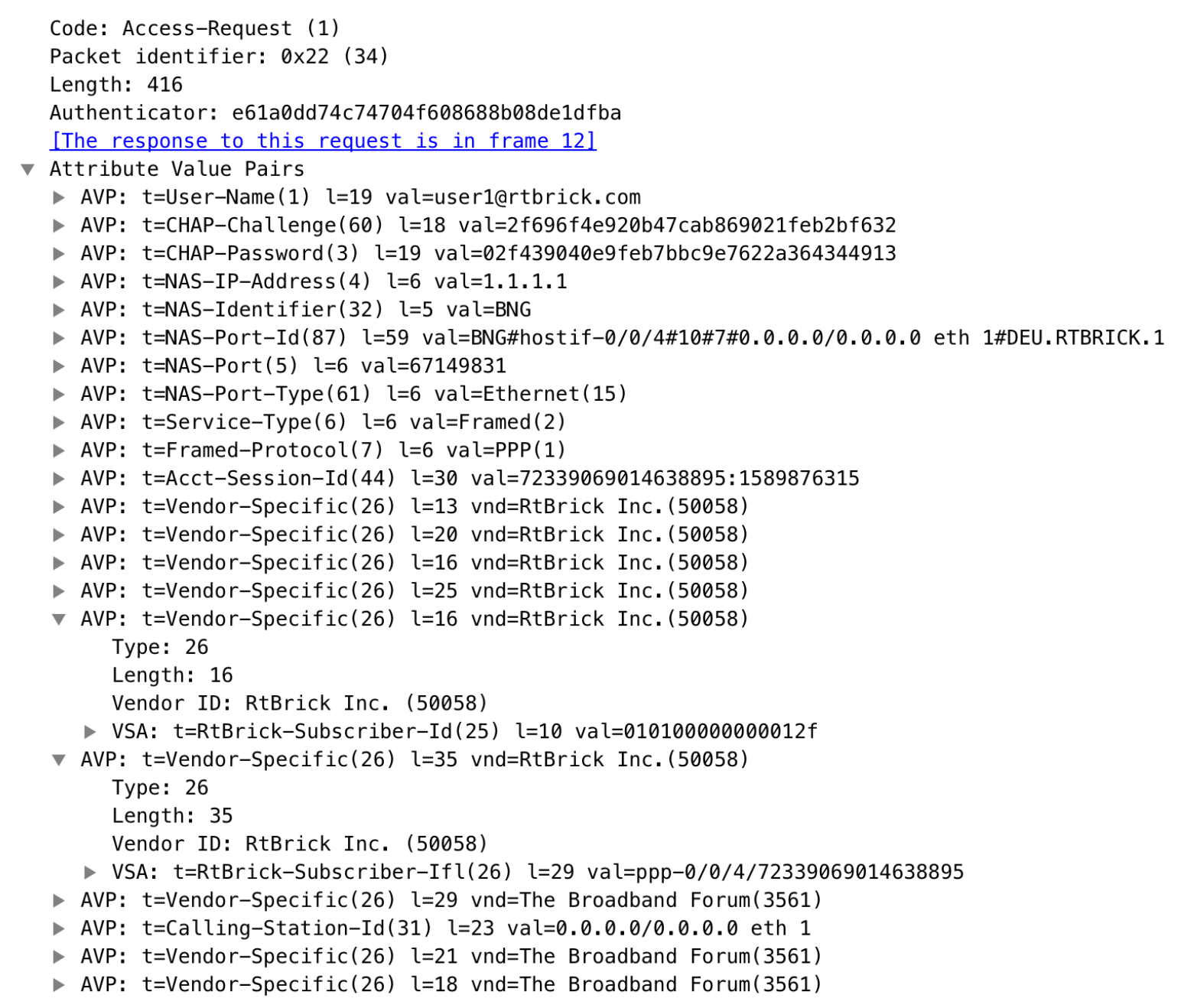
The subscriber daemon requests authentication in RADIUS access-request messages before permitting subscribers access. Accounting servers handle accounting records for subscribers. The subscriber daemon transmits RADIUS accounting-start, interim, and stop messages to the servers. Accounting is the process of tracking subscriber activity and network resource usage in a subscriber session. This includes the session time called time accounting and the number of packets and bytes transmitted during the session called volume accounting. A RADIUS server can behave as a change of authorization (CoA) client, allowing dynamic changes for subscriber sessions. The subscriber daemon supports both RADIUS CoA messages and disconnects messages. CoA messages can modify the characteristics of existing subscriber sessions without loss of service, disconnect messages can terminate subscriber sessions. Each RADIUS request from the subscriber daemon includes the RADIUS accounting-session-id attribute (type 44) with a format that is configurable in the AAA configuration profile and includes at least the subscriber-id to identify the corresponding subscriber. The default format (<subscriber-id>.<timestamp>) includes also a Unix timestamp to ensure that the tuple of NAS-Identifier (e.g. hostname) and Accounting-Session-Id is global and unique to be usable as a key in RADIUS databases.
Additionally, to subscriber-id and accounting-session-id each subscriber consists also of a subscriber-ifl build based on
physical port information and subscriber-id (ifp: ifp-0/0/1 and
subscriber-id: 72339069014638610 → subscriber-ifl: ppp-0/0/1/72339069014638610)
which is required as a handle in the RBFS forwarding infrastructure.
|
|
The subscriber-id is an unsigned 64bit integer which is shown as a hex number in Wireshark. |
Each subscriber is formed based on configuration profiles and individual settings retrieved via RADIUS. Conflicts between RADIUS-defined attributes and profile attributes are solved by prioritizing those received from RADIUS which is common best practice for broadband access concentrators. New subscribers are signalled via RADIUS access request and either accepted by RADIUS access-accept or rejected by RADIUS access-reject message from the RADIUS server. The RADIUS access-accept includes all attributes required to form the subscriber like IP addresses, DNS servers, and referenced configuration profiles. Some of those attributes can be changed by RADIUS dynamically using CoA requests without disconnecting the subscriber.
1.3.1. RADIUS Accounting
A RADIUS Acct-Status-Type attribute is used by the RADIUS client (subscriber daemon) to mark the start of accounting (for example, upon booting) by specifying Accounting-On and to mark the end of accounting (for example, just before a scheduled reboot) by specifying Accounting-Off. This message is often used by RADIUS servers to automatically close/terminate all open accounting records/sessions for the corresponding client, and therefore must not be sent to servers belonging to a profile that was already used/started for accounting.
Per default, the assumption is that all servers referenced by a RADIUS profile share the same states and therefore accounting-on must be only sent to one of those before the first accounting-start is sent.
RADIUS Accounting-On/Off messages are optionally enabled in the RADIUS profile configuration (RADIUS Profile Configuration) using the accounting-on-off attribute. The additional attribute accounting-on-wait prevents any new session until accounting has started meaning that the Accounting-On response is received.
|
|
Accounting-Off is currently not implemented! |
RADIUS accounting requests are often used for billing and therefore should be able to store and retry over a more extended period (commonly up to 24 hours or more) which can be optionally enabled in the RADIUS profile configuration using the accounting-backup attribute. The maximum backup accounting hold time in seconds is defined in the attribute accounting-backup-max.
1.3.2. RADIUS Redundancy
It is possible to configure multiple RADIUS authentication and accounting servers for redundancy and or load-balancing.
The following two algorithms are supported:
-
DIRECT (default): Requests are sent to the same server where the last request was sent. If the subscriber daemon receives no response from the server, requests are sent to the next server.
-
ROUND-ROBIN: Requests are sent to the server following the one where the last request was sent. If the subscriber daemon router receives no response from the server, requests are sent to the next server.
1.3.3. RADIUS NAS-Port-id
The RADIUS attribute NAS-Port-Id (87) is constructed as shown below:
<NAS-IDENTIFIER>#<IFP>#<OUTER-VLAN>#<INNER-VLAN>#<ACI>#<ARI>
The Agent-Circuit-Id (ACI) and Agent-Remote-Id (ARI) are replaced with an empty string (##) if not available.
1.4. PPP over Ethernet (PPPoE)
PPP over Ethernet (PPPoE) is the common standard for internet access in the market.
|
|
Currently, RBFS only supports PPPoE subscriber sessions with EtherType 0x8100 (802.1Q); it does not support EtherType 0x88a8 (802.1ad). |
1.4.1. PPPoE Session-Id
As defined in RFC2516, the PPPoE session-id field is an unsigned 16-bit number with the reserved values 0 for PADI/PADO and 65535 for future use. The session-id will be guaranteed unique per broadcast domain (IFP and VLANs) and client MAC address, but either not unique per device or app instance. The session-id changes every time the session is reconnected.
1.4.2. PPPoE Service-Name
The last service name from the request (PADI or PADR) is internally ignored but copied to the response (PADO or PADS). If the request does not include any service name, the response includes the default service name access for compatibility with some clients like Linux pppd.
1.4.3. PPPoE AC-Cookie
This TAG is actually used to aid in protecting against denial-of-service attacks, but it is primarily used in RBFS to decide if a received PADR is a retry for an already answered (PADS send) one. The value itself is unpredictable and generated securely but it does not protect from reply attacks.
If a client receives this TAG in PADO, it MUST return the TAG unmodified in the following PADR. The TAG_VALUE is binary data of any value and length and is not interpreted by the Host.
The AC-Cookie is generated based on 8-bit salt followed by MD5 hash of salt, client MAC and dynamic PPPoE cookie secret.
    0                   1                   2
    0 1 2 3 4 5 6 7 8 9 0 1 2 3 4 5 6 7 8 9 0 1 2 3 4
    +-+-+-+-+-+-+-+-+-+-+-+-+-+-+-+-+-+-+-+-+-+-+-+-+
    | SALT          | MD5                           |
    +-+-+-+-+-+-+-+-+-+-+-+-+-+-+-+-+-+-+-+-+-+-+-+-+
The PPPoE cookie secret is randomly generated during the PPPoE daemon startup.
The AC-Cookie in the PADR creating the session is stored in the PPPoE PPP session object. For any received PADR it can be checked if there is a session on the same broadcast domain (IFP and VLAN’s) and MAC with the same AC-Cookie. In this case, the PADS is just retried.
If the broadcast domain and MAC is equal but AC-Cookie is different, this PADR must be considered as a new request.
This allows to separate two different PPPoE sessions on the same VLAN from the same MAC as frequently used by some service providers.
1.4.4. PPPoE Session Limit
A customer line is typically represented by one (single-tagged) or two VLAN (double-tagged) on a physical interface with a limitation to one session, which is also called the 1:1 VLAN mode.
In some cases, the customer CPE will set up multiple PPPoE sessions on a single VLAN which requires MAC limitations greater than one but less or equal to the per VLAN limitation.
Therefore RBFS supports two different session limitations in the access interface configuration (Access Interface Configuration), one per VLAN (max-subscribers-per-vlan) and an additional per client MAC address (max-subscribers-per-mac) both set to 1 per default as required for 1:1 VLAN mode.
The limitation of sessions per client MAC address must be less or equal the sessions per VLAN and the default set to one for both limits.
1.4.5. PPPoE 1:1 and N:1 Support
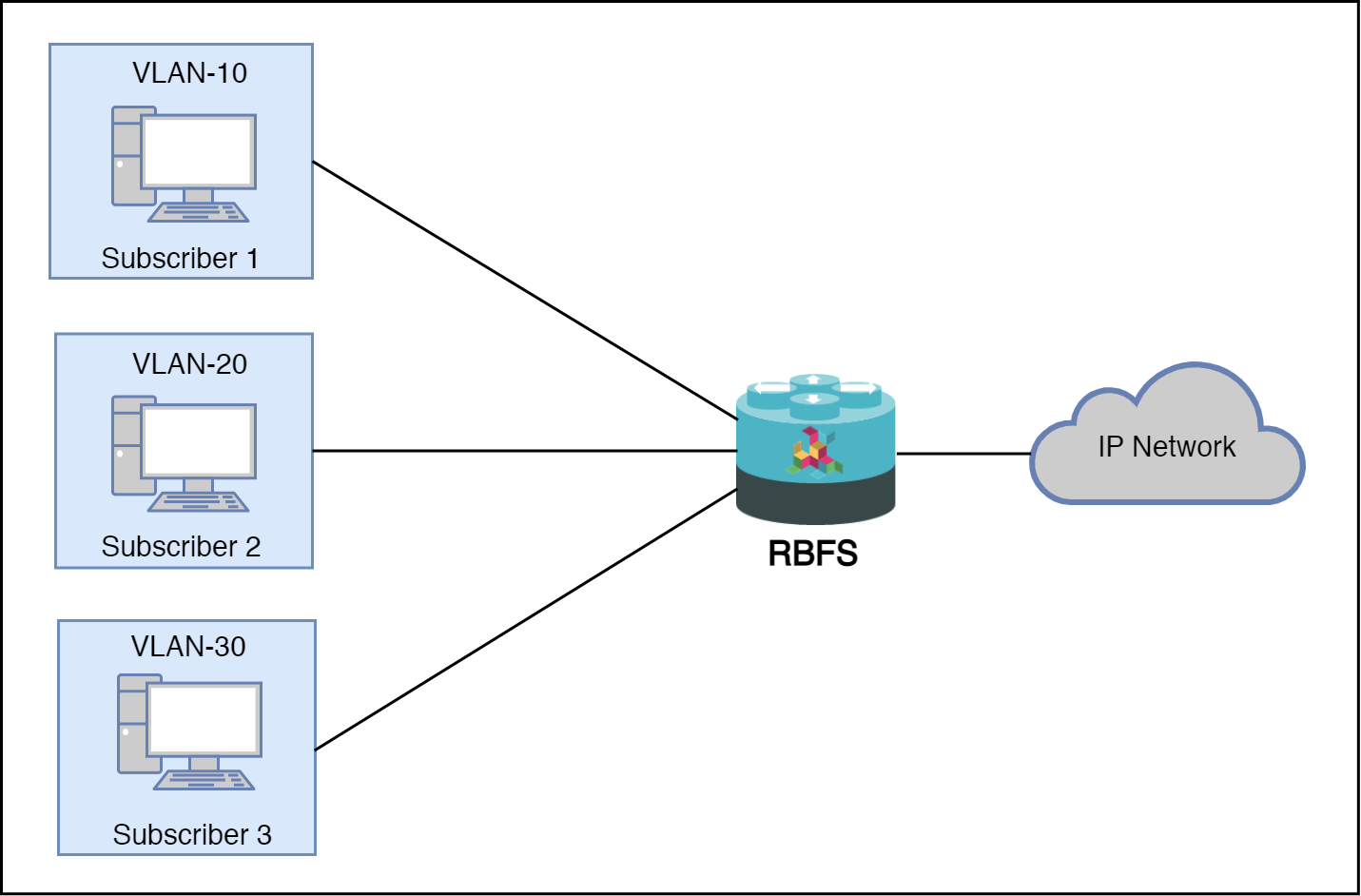
RBFS supports both 1:1 VLAN (VLAN Per Subscriber) and N:1 VLAN (shared VLAN) models for subscriber traffic for PPPoE subscribers.
1.4.5.1. 1:1 VLAN (VLAN-per-subscriber) Model
In the 1:1 VLAN model, there is a unique dedicated customer VLAN for a subscriber, that is one VLAN per Subscriber. This model establishes a unique path between each subscriber interface and the router for data transmission by providing traffic separation for every subscriber.
1:1 model operations are relatively simple as it provides one-to-one mapping of specific VLANs to specific subscribers. New services can be added easily without affecting other subscribers and services with this model. However, in a large-scale deployment, this model demands highly scalable and robust routers that can manage many hundreds of VLANs.
The following diagram shows a dedicated customer VLAN for a subscriber, that is, one VLAN per Subscriber.
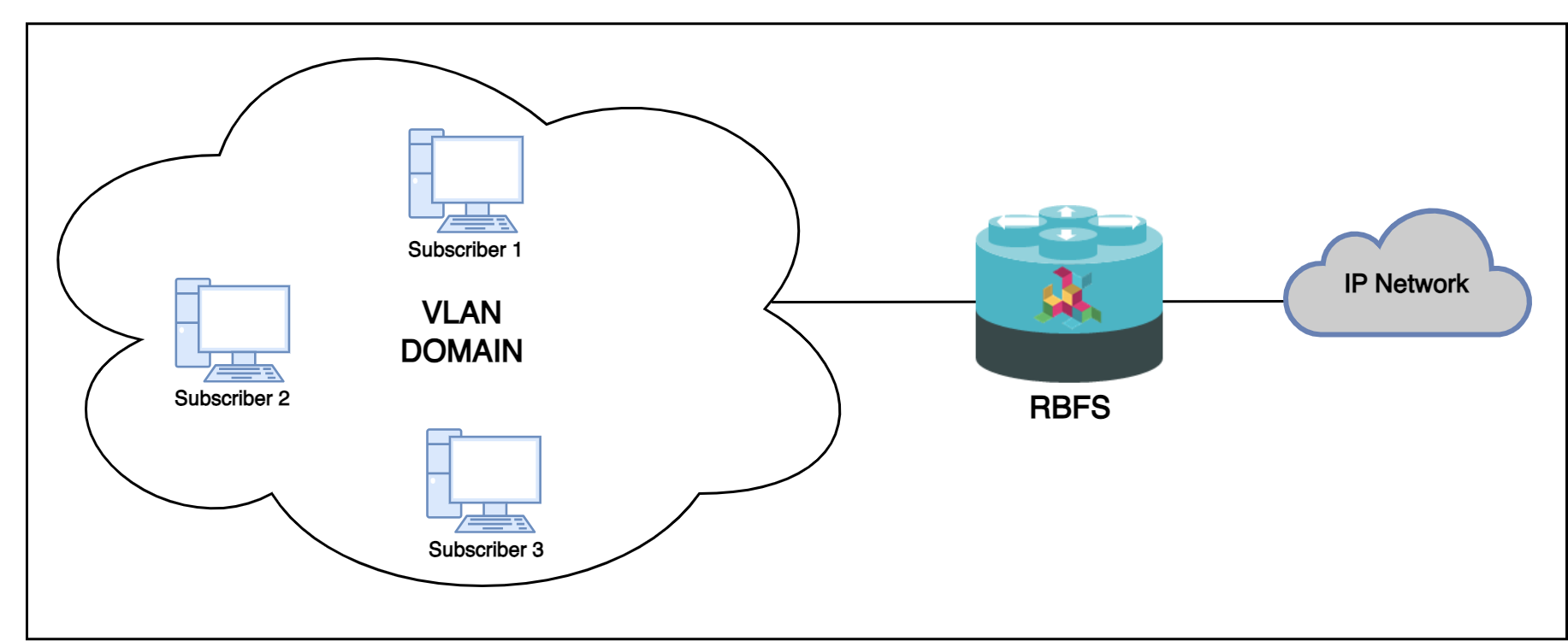
1.4.5.2. N:1 VLAN (Shared VLAN) Model
The Shared VLAN model provides many-to-one (N:1) subscriber-to-service connectivity. This model provides a single VLAN to many subscribers. Unlike in the 1:1 model, in which the VLAN is dedicated to a customer, N:1 provides a shared VLAN to many subscribers, and this VLAN carries all types of service (i.e., data, voice, video, etc.). One disadvantage of shared VLAN is the lack of logical isolation between user sessions at the VLAN level.
The following diagram shows a single VLAN that is connected to many subscribers.
1.4.6. PPPoE MTU Profiles
The PPP protocol allows each endpoint to negotiate a maximum receive unit (MRU). This MRU is applied as the maximum transmission unit (MTU) on the other end of the PPP connection. Each endpoint negotiates its own MRU with the other peer. Thus using a different MTU per direction is not uncommon for PPP, even if not desired.
Bare metal switch hardware is typically limited in the number of supported MTU values.
So RBFS has introduced the concept of MTU profiles with different types like physical,
ip or pppoe. The last one is reserved for use with PPPoE sessions and applies to
IPv4 and IPv6 traffic.
supervisor@switch: cfg> show config forwarding-options mtu-profile
{
  "rtbrick-config:mtu-profile": [
    {
      "mtu-profile-name": "IP-MTU-1500",
      "size": 1500,
      "type": "ip",
      "action": "redirect-to-cpu"
    },
    {
      "mtu-profile-name": "IP-MTU-9202",
      "size": 9202,
      "type": "ip",
      "action": "drop"
    },
    {
      "mtu-profile-name": "PPPoE-MTU-1320",
      "size": 1320,
      "type": "pppoe",
      "action": "redirect-to-cpu"
    },
    {
      "mtu-profile-name": "PPPoE-MTU-1456",
      "size": 1456,
      "type": "pppoe",
      "action": "redirect-to-cpu"
    },
    {
      "mtu-profile-name": "PPPoE-MTU-1472",
      "size": 1472,
      "type": "pppoe",
      "action": "redirect-to-cpu"
    },
    {
      "mtu-profile-name": "Port-MTU-9216",
      "size": 9216,
      "type": "physical",
      "action": "drop"
    },
    {
      "mtu-profile-name": "__default_pppoe__",
      "size": 1492,
      "type": "pppoe",
      "action": "redirect-to-cpu"
    }
  ]
}
A configured size of 1492 bytes limits the size of the IPv4 or IPv6 header plus payload.
|
|
The physical access interface should be configured with an MTU profile large enough to serve all PPPoE MTU profiles, including the additional overhead for PPPoE and VLAN headers. Further details about interface MTU profiles can be found in the Interfaces Configuration Guide. |
The action could be either drop or redirect-to-cpu. The action drop silently discards
all oversized packets. The action redirect-to-cpu punts oversized packets to the CPU where
those could be either fragmented or dropped with ICMP response.
The Q2C platform supports up to 8 MTU profiles in total. The amount of pppoe profiles is limited to 6
including the default profile _default_pppoe_. The default profile can’t be deleted but overwritten
to change size and action.
supervisor@switch: cfg> show config forwarding-options mtu-profile __default_pppoe__
{
  "rtbrick-config:mtu-profile": [
    {
      "mtu-profile-name": "__default_pppoe__",
      "size": 1492,
      "type": "pppoe",
      "action": "redirect-to-cpu"
    }
  ]
}
The command show pppoe mtu-profile lists all PPPoE MTU profiles
in increasing order, with two statistics about the exact and best match.
supervisor@switch: op> show pppoe mtu-profile
Profile                MTU      Exact Match      Best Match
PPPoE-MTU-1320         1320     0                0
PPPoE-MTU-1456         1456     0                0
PPPoE-MTU-1472         1472     0                0
__default_pppoe__      1492     0                0
If a client requests an MRU via PPP LCP Configure-Request, this value is used to search for an appropriate MTU profile. This is done by iterating over the ordered list of MTU profiles, as long as the received MRU is greater than the MTU size. If the requested MRU is found in the list of MTU profiles, the exact match counter is incremented, and the MRU is accepted.
In case the requested MRU is not found, the last MTU profile found is selected
and the best match counter is incremented. The selected MTU is then offered to the
client via PPP LCP Configure-Nak. If the offered MRU is not accepted by the client
after three offers, a fallback profile is applied. This means that the requested MRU
from the client is accepted, but the largest pppoe MTU profile is applied.
This algorithm was built to ensure most client compatibility.
Let’s assume a client requests the MRU 1482, but only profiles for 1472 and 1492 are configured. In this case, 1472 is offered as the best match via PPP LCP Configure-Nak. The client could either accept the offer by sending a PPP LCP Configure-Request with the MRU 1472 or try again with the original value of 1482. This is repeated up to three times before the fallback profile is applied. In this case, the client MRU of 1482 is accepted but the maximum MTU of 1492 is applied. The majority of CPE devices support TCP MSS clamping using the negotiated MRU of 1482. So at least TCP traffic is still limited to the negotiated MRU. This is the reason for applying a larger MTU profile as the fallback profile. It’s also common that a CPE still accepts packets larger than the negotiated MRU.
The exact and best match counters can be used by operators to verify if the configured MTU profiles fit their environment or should be adopted.
The negotiated MRU and applied MTU can be verified with the following command for every single PPPoE session.
user@switch: op> show pppoe session 72339069014638648 detail
Subscriber-Id: 72339069014638648
    State: ESTABLISHED
    ...
    PPP LCP:
        ...
        MRU: 1492 Peer: 1492
        MTU: 1492 Profile: __default_pppoe__
    ...
For L2TPv2 tunneled PPPoE sessions, the MTU is enforced by the LNS. It’s usual behavior that the LNS renegotiates the MTU. So LAC may not know the actual MTU. This is the reason why RBFS does not apply an MTU profile for such sessions.
RBFS overwrites the selected MTU profile with default_l2tp for L2TPv2 sessions. This profile must
be explicitly created, otherwise it is ignored. The action must be drop because ICMP or fragmentation
is not supported for tunneled sessions.
supervisor@switch: cfg> show config forwarding-options mtu-profile __default_l2tp__
{
    "rtbrick-config:mtu-profile": [
      {
        "mtu-profile-name": "__default_l2tp__",
        "size": 1492,
        "type": "pppoe",
        "action": "redirect-to-cpu"
      }
    ]
  }
This configuration allows to optionally enforce an MTU on LAC if needed.
1.4.7. PPPoE VLAN Profiles
This chapter describes the VLAN profile feature. If enabled for the access interface, then incoming sessions (e.g. PPPoE PADI/PADR) are not honored unless matching vlan-profile is found.
The VLAN profiles must be added to the table global.vlan.profile owned by PPPoE daemon.
All entries in this table are ephemeral and therefore lost after reboot or PPPoE daemon restart.
Example:
{
    "table": {
        "table_name": "global.vlan.profile"
    },
    "objects": [
        {
            "attribute": {
                "ifp_name": "ifp-0/1/2",
                "outer_vlan_min": 128,
                "outer_vlan_max": 128,
                "inner_vlan_min": 1,
                "inner_vlan_max": 4095,
                "access_profile_name": "access-profile-vlan"
            }
        }
    ]
}
1.4.8. PPPoE Dual-Stack IPv4/IPv6 with DHCPv6
The whole IPv6 control plane of a PPPoE session like ICMPv6 router-solicitation (RS), ICMPv6 router-advertisement (RA) and DHCPv6 is handled in the PPPoE daemon (pppoed).
The PPPoE daemon handles received router solicitations by responding with router advertisements and is sending frequent router advertisements based on configured intervals.
The other-config flag in the router-advertisement is automatically set if DHCPv6 is enabled for this particular subscriber. This flag signals that there is more information available via DHCPv6.
DHCPv6 over PPPoE is different to DHCPv6 over Ethernet because of the special characteristics of point-to-point protocols. DHCPv6 over PPPoE is supporting delegated IPv6 prefixes (IA_PD) and DNS options only. Unsupported IA options (IA_NA and IA_TA) or options that can be served will be rejected with status code options as defined per RFC.
The delegated IPv6 prefix served by DHCPv6 will be assigned to the subscriber via RADIUS
or local pool regardless of the protocols negotiated with the client. DHCPv6 was primarily
designed for use in Ethernet networks. The fact that Ethernet is connectionless requires
that DHCPv6 servers must manage releases for the clients and free them automatically if a lease
expires. Such extensive release management is not needed for connection-oriented protocols
like PPPoE where addresses are assigned to the PPPoE session. This fact allows to
implementing DHCPv6 nearly stateless on the server side by just tracking if an assigned prefix
is assigned or released. This is tracked in the attribute ipv6pd_negotiated of the PPPoED/SubscriberD (global.ppp.1.subscriber.result) result object and copied to the
actual subscriber object (local.access.subscriber). As this use case is covered by PPPoE, there is no lease expiry implemented.
The delegated-prefix is added to the subscriber-ifl only if negotiated and removed if not negotiated. The presence of delegated prefix in the subscriber-ifl is used by IFMD to add or remove the forwarding entry.
If DHCPv6 is enabled but no delegated prefix provided, only DNS is served in response if available.
1.4.8.1. PPPoE DHCPv6 Server DUID
The DHCPv6 server identifier DUID is generated based on IP6CP negotiated interface-identifier as shown below:
    0                   1                   2                   3
    0 1 2 3 4 5 6 7 8 9 0 1 2 3 4 5 6 7 8 9 0 1 2 3 4 5 6 7 8 9 0 1
    +-+-+-+-+-+-+-+-+-+-+-+-+-+-+-+-+-+-+-+-+-+-+-+-+-+-+-+-+-+-+-+-+
    |     DUID-Type 3 (DUID-LL)     |    hardware type 27 (EUI64)   |
    +-+-+-+-+-+-+-+-+-+-+-+-+-+-+-+-+-+-+-+-+-+-+-+-+-+-+-+-+-+-+-+-+
    |                      interface-identifier                     |
    |                                                               |
    +-+-+-+-+-+-+-+-+-+-+-+-+-+-+-+-+-+-+-+-+-+-+-+-+-+-+-+-+-+-+-+-+
1.5. Layer Two Tunneling Protocol (L2TPv2)
This chapter describes the RtBrick Layer Two Tunneling Protocol (L2TPv2) implementation. This document describes also the corresponding configuration (Configuration Commands) and operations (Operations) for PPPoE access services with PPP tunneling using the Layer Two Tunneling Protocol version 2 (L2TPv2) on RtBRick FullStack (RBFS).
Typically, a user obtains a Layer 2 (L2) point-to-point connection to a Broadband Network Gateway (BNG) using the PPPoE protocol as described in RFC 2516 and runs PPP over that connection. In the most common case, the L2 termination point and PPP session endpoint reside on the same physical device. Tunneling protocols, such as L2TPv2 provide a dynamic mechanism for extending PPP by allowing the L2 and PPP endpoints reside on different devices that are interconnected by an IP network. This separation allows the actual processing of PPP packets to be divorced from the termination of the L2 circuit. The L2TP access concentrator (LAC) physically terminates the L2 connection and tunnels the PPP packets across an IP network to the L2TP network server (LNS). The LNS then terminates the logical PPP connection.
|
|
RFC and draft compliance are partial except as specified. |
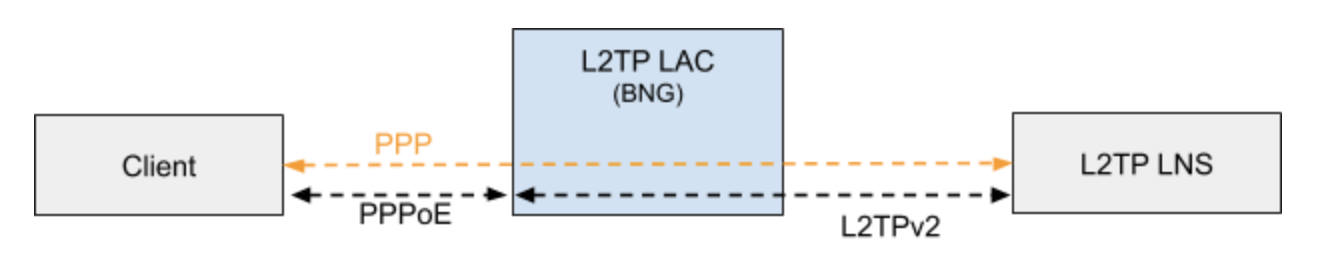
1.5.1. L2TP LAC
The L2TP Access Concentrator (LAC) is a node that acts as one side of an L2TP tunnel endpoint, and is a peer to the L2TP Network Server L2TP LNS. The LAC sits between a LNS and a remote system, and forwards packets to and from each.
1.5.2. L2TP LNS
The L2TP Network Server (LNS) is a node that acts as one side of an L2TP tunnel endpoint and is a peer to the L2TP Access Concentrator L2TP LAC. The LNS is the logical termination point of a PPP session that is being tunneled from the remote system by the LAC.
|
|
The LNS role is currently not supported! |
1.5.3. L2TP Tunnel Selection
Each new session creates a session request object (local.l2tp.session.request) to track the tunnel selection progress, the currently selected ones, and which are already tried. This object is automatically deleted if the session setup is successful.
All tunnels in state DEAD are skipped in the tunnel selection but considered at the end if no other tunnels are available. Tunnels with a session limit reached are not considered for further sessions. To select a tunnel, the L2TP daemon first generates list of preferred tunnels based on tunnel preference, where the lowest value has the highest priority. The configured L2TP tunnel selection algorithm decides how to select a tunnel out of the remaining tunnels with the same preference. The RANDOM algorithm selects the tunnel randomly whereas BALANCED selects the least filled tunnel based on a number of sessions.
Following the L2TP tunnel pool order/priority in case, there are multiple pools available for a single subscriber:
-
RADIUS defined tunnel (RFC2866)
-
RADIUS VSA (RtBrick-L2TP-Pool) or local user profile
-
L2TP configuration profile
1.5.4. L2TP Control Channel
The control channel is responsible for the orderly passing of control messages between the tunnel endpoints and acts as a transport layer for reliable delivery of control messages and tunnel keep alive services for the tunnel.
Each L2TP tunnel is split into the actual tunnel object with all the information exchanged during tunnel establishment plus the FSM state and a separate control channel with the sequence numbers, window size, and thresholds changed with every sent and received packet.
RBFS sent a ZLB ACK only if there are no further messages waiting in queue for that peer, as well as to acknowledge multiple packets at once.
The HELLO keep-alive messages are also part of the control channel and only send if there is no other message sent if the queue is empty and no other message send during the hello interval.
1.5.5. L2TP Access Line Information (RFC5515)
1.5.5.1. Connect-Speed-Update-Notification (CSUN)
The Connect-Speed-Update-Notification (CSUN) is an L2TP control message sent by the LAC to the LNS to provide transmit and receive connection speed updates for one or more sessions.
|
|
This implementation will send one CSUN request per session! |
CSUN requests are disabled per default and can be enabled in the L2TP profile (L2TP Profile Configuration).
CSUN messages are defined in RFC5515, which is not widely supported. Therefore those messages are marked as not mandatory in RBFS to allow interwork with LNS servers not supporting RFC5515.
RFC2661:
The Mandatory (M) bit within the Message Type AVP has special
meaning. Rather than an indication of whether the AVP itself
should be ignored if not recognized, it is an indication as to
whether the control message itself should be ignored. Thus, if the
M-bit is set within the Message Type AVP and the Message Type is
unknown to the implementation, the tunnel MUST be cleared.  If the
M-bit is not set, then the implementation may ignore an unknown
message type.
|
|
RFC and draft compliance are partial except as specified. |
1.5.5.2. Connect-Speed-Update-Request (CSURQ)
The Connect-Speed-Update-Request (CSURQ) is an L2TP control message sent by the LNS to the LAC to request the current transmission and receive connection speed for one or more sessions.
|
|
Sending or responding to CSURQ requests is currently not supported! |
1.5.5.3. Access Line Information L2TP Attribute Value Pair Extensions
The corresponding access line information for a subscriber is included in the ICRQ message as defined in RFC5515.
1.5.5.4. Connect Speed Values
The default value for TX and RX Connect Speed is set to 1000000000 (1G) which is replaced by the actual data rate upstream/downstream of the corresponding access line information object or directly set using the RADIUS attributes RtBrick-L2TP-Tx-Connect-Speed (42) and RtBrick-L2TP-Rx-Connect-Speed (43).
1.6. IPoE
IP-over-Ethernet (IPoE) is a popular alternative to PPPoE based access using DHCP for IPv4 and DHCPv6 for IPv6 where both protocols are handled in the IPoE daemon (ipoed).
IPoE subscribers are identified by IFP, optional VLAN and client MAC address.
The dynamic creation of IPoE subscribers is triggered by the first DHCPv4 discovery or
DHCPv6 solicit request received. Any response is postponed until the subscriber is
successfully authenticated using known authentication methods like none, local
or RADIUS. For DHCP mode server all addresses are assigned during authentication to the subscriber and used by DHCPv4 and DHCPv6 to handle client requests. For the DHCP relay mode, all IP addresses are allocated by an external DHCP server.
IPoE subscribers will be terminated automatically if all protocol bindings are deleted.
1.6.1. IPoE 1:1 VLAN Support
RBFS supports 1:1 VLAN (VLAN Per Subscriber) model for subscriber traffic for IPoE subscribers. In the 1:1 VLAN model, there is a unique dedicated customer VLAN for a subscriber, that is one VLAN per Subscriber. This model establishes a unique path between each subscriber interface and the router for data transmission by providing traffic separation for every subscriber.
The following diagram shows a dedicated customer VLAN for a subscriber, that is, one VLAN per Subscriber.
1.6.2. IPoE Session Limit
A customer line is typically represented by one (single-tagged) or two VLAN (double-tagged) on a physical interface with a limitation to one subscriber, which is also called the 1:1 VLAN mode.
IPoE subscribers are implicitly limited to max one per MAC address, as client MAC address is used as part of the key to identify subscribers.
1.6.3. IPoE Username
For each IPoE subscriber, a username is generated automatically using
the client’s MAC address followed by @ipoe.
Example: fe:08:e8:ea:1d:32@ipoe
1.6.4. IPoE DHCPv6 Server DUID
The generated DHCPv6 server identifier DUID is from type 3 (DUID-LL) with hardware type 27 (EUI64) and IFP MAC address to derive the EUI64 interface identifier.
    0                   1                   2                   3
    0 1 2 3 4 5 6 7 8 9 0 1 2 3 4 5 6 7 8 9 0 1 2 3 4 5 6 7 8 9 0 1
    +-+-+-+-+-+-+-+-+-+-+-+-+-+-+-+-+-+-+-+-+-+-+-+-+-+-+-+-+-+-+-+-+
    |     DUID-Type 3 (DUID-LL)     |    hardware type 27 (EUI64)   |
    +-+-+-+-+-+-+-+-+-+-+-+-+-+-+-+-+-+-+-+-+-+-+-+-+-+-+-+-+-+-+-+-+
    |                      interface-identifier                     |
    |                                                               |
    +-+-+-+-+-+-+-+-+-+-+-+-+-+-+-+-+-+-+-+-+-+-+-+-+-+-+-+-+-+-+-+-+
1.6.5. IPoE DHCP Relay
When IPoE is configured on relay mode, the system relies on an external DHCP server for IP address allocation and client configuration functions. The DHCP server contains a pool of IP addresses, and from that pool, it allocates addresses to subscribers. RBFS acts as a DHCP relay during its interaction with the DHCP server. The feature allows multiple RBFS instances to use a single centralized DHCP server for their IP allocation.
For information on how to configure IPoE in relay mode, see the section DHCPv4.
2. Configuration
The following sections describe Subscriber Management configuration syntax and commands.
2.1. Configuration Hierarchy
The main interface configuration for a physical interface (ifp) and associated VLANs is related to a series of profiles that hold parameters for authentication with AAA, services like IGMP and MLD, access methods like PPPoE and the like, and so on. The overall structure of this configuration and profile system is shown in Figure 2.
All of the access configuration and profile sections are edited under the access top-level hierarchy of the configuration.
supervisor@switch: cfg> set access
  <cr>
  aaa-profile           Global AAA profile configuration
  access-profile        Global access profile configuration
  chassis-id            Chassis id for this node <0-15>
  dhcp-relay            Global DHCP relay configuration
  dhcp-server           Global DHCP server configuration
  dhcpv6-server         Global DHCP server configuration
  interface             Global interface profile configuration
  l2bsa                 Global access l2bsa configurations
  l2tp-pool             Global L2TPv2 pool configuration
  l2tp-profile          Global L2TPv2 profile configuration
  pool                  Global address pool configuration
  radius-profile        Global AAA RADIUS profile configuration
  radius-server         Global RADIUS server configuration
  service-profile       Global service profile configuration
  user-profile          Global user profile configuration
Detailed descriptions of each configuration and profile can be found in the following chapters.This configuration guide starts with the interface configuration which is the entry point for every new subscriber followed by mandatory access and AAA configuration profiles.
-
interface-config Access Interface Configuration
-
access-profile Access Profile Configuration
-
aaa-profile AAA Profile Configuration
The second part explains the optional configurations.
-
radius-profile RADIUS Profile Configuration
-
radius-server RADIUS Server Configuration
-
service-profile Service Profile Configuration
-
l2tp-profile L2TP Profile Configuration
-
address-pools Address Pool Configuration
The user-profile and l2tp-pool are the only component not referenced by name. The key here is the user or pool name.
-
user-profile User Profile Configuration
-
l2tp-pool L2TP Tunnel Pool Configuration
2.2. Configuration Commands
2.2.1. Access Interface Configuration
Table: global.access.interface.config
Although there is no correct way to configure subscriber management, it makes most sense to proceed from mandatory configurations and profiles to optional ones. First and foremost, among these mandatory configuration items is the access interface configuration which is the anchor point for almost all further access configurations.
The interface configuration assigns the access type, access profile (Access Profile Configuration), AAA profile (AAA Profile Configuration) and further optional attributes to the matching physical interface (IFP) and VLAN.
Multiple interface configurations per IFP with disjoint VLAN ranges are supported.
The way that the interface configuration relates to all subscriber management configuration tasks is shown in the picture below.
Note that there can be more than one interface configured for subscriber management and each interface can reference the same profiles.
There are four major configuration tasks for the access interface:
-
Configure the physical interface name (IFP) and VLAN range
-
Configure the mandatory access type (PPPoE or IPoE)
-
Configure the mandatory access profile
-
Configure the mandatory AAA profile
-
Configure optional attributes like service profile or session limit
2.2.1.1. Configuring Access Interfaces
Access interfaces can be configured without VLAN tags (untagged) and with one (single tagged) or two (double tagged) VLAN tags.
supervisor@switch: cfg> set access interface
  <cr>
  double-tagged         Double tagged access
  single-tagged         Single tagged access
  untagged              Untagged access

supervisor@switch: cfg> set access interface untagged ifp-0/0/0
  <cr>
  aaa-profile-name          AAA profile name
  access-profile-name       Access profile name
  access-type               Access service type
  max-subscribers-per-mac   Restrict maximum subscribers per MAC address
  max-subscribers-per-vlan  Restrict maximum subscribers per VLAN
  service-profile-name      Service profile name
  vlan-profile-enable       Enable VLAN profiles
The following example shows an untagged access interface.
supervisor@switch: cfg> show config access interface untagged ifp-0/0/0
{
  "rtbrick-config:untagged": {
    "interface-name": "ifp-0/0/0",
    "access-type": "PPPoE",
    "access-profile-name": "pppoe-dual",
    "service-profile-name": "service-profile1",
    "aaa-profile-name": "aaa-radius",
    "vlan-profile-enable": "true",
    "max-subscribers-per-vlan": 1,
    "max-subscribers-per-mac": 1
  }
}
| Attribute | Description | ||
|---|---|---|---|
access-type |
The mandatory access type attribute define the access protocol used for this interface. Values: PPPoE or IPoE |
||
access-profile-name |
The name of the mandatory access profile (Access Profile Configuration). |
||
aaa-profile-name |
The name of the mandatory AAA profile (AAA Profile Configuration). |
||
service-profile-name |
This option allows assigning an optional service profile (Service Profile Configuration) which can be dynamically overwritten via RADIUS. |
||
max-subscribers-per-vlan |
This option defines the maximum number of subscribers per IFP and VLAN. A value of 1 will implicitly set the VLAN mode to 1:1, where any value grater than 1 means N:1. Default: 1 Range: 1 - 65535
|
||
max-subscribers-per-mac |
Maximum number of subscribers per IFP, VLAN, and MAC. This option must be less or equal to the max-subscribers-per-vlan. Default: 1 Range: 1 - 65535 |
||
vlan-profile-enable |
If enabled, incoming PPPoE sessions (PPPoE PADI/PADR) are not honored unless matching vlan-profile is found
in the table Default: false |
||
gateway-ifl |
This options selects the IPoE gateway IFL (unnumbered source IFL) which is typically a loopback interface used as a gateway for IPoE subscribers. |
2.2.1.2. Configuring Untagged Interfaces
supervisor@switch: cfg> set access interface untagged
  <interface-name>      Name of the physical interface

supervisor@switch: cfg> set access interface untagged ifp-0/0/0
  <cr>
  aaa-profile-name          AAA profile name
  access-profile-name       Access profile name
  access-type               Access service type
  max-subscribers-per-mac   Restrict maximum subscribers per MAC address
  max-subscribers-per-vlan  Restrict maximum subscribers per VLAN
  service-profile-name      Service profile name
  vlan-profile-enable       Enable VLAN profiles

supervisor@switch: cfg> set access interface untagged ifp-0/0/0 access-type PPPoE
supervisor@switch: cfg> set access interface untagged ifp-0/0/0 access-profile-name pppoe-dual
supervisor@switch: cfg> set access interface untagged ifp-0/0/0 aaa-profile-name aaa-radius
supervisor@switch: cfg> commit
supervisor@switch: cfg> show config access interface untagged ifp-0/0/0
{
  "rtbrick-config:untagged": {
    "interface-name": "ifp-0/0/0",
    "access-type": "PPPoE",
    "access-profile-name": "pppoe-dual",
    "aaa-profile-name": "aaa-radius"
  }
}
|
|
Untagged interfaces are not supported on Broadcom QMX and QAX platforms. |
2.2.1.3. Configuring Single VLAN Tagged Interfaces
The VLAN range 128 - 4000 includes VLAN 128, 4000, and VLAN identifiers between.
supervisor@switch: cfg> set access interface single-tagged
  <interface-name>      Name of the physical interface

supervisor@switch: cfg> set access interface single-tagged ifp-0/0/0
  <outer-vlan-min>      Outer VLAN min

supervisor@switch: cfg> set access interface single-tagged ifp-0/0/0 128
  <outer-vlan-max>      Outer VLAN max

supervisor@switch: cfg> set access interface single-tagged ifp-0/0/0 128 3000
  <cr>
  aaa-profile-name          AAA profile name
  access-profile-name       Access profile name
  access-type               Access service type
  max-subscribers-per-mac   Restrict maximum subscribers per MAC address
  max-subscribers-per-vlan  Restrict maximum subscribers per VLAN
  service-profile-name      Service profile name
  vlan-profile-enable       Enable VLAN profiles

supervisor@switch: cfg> set access interface single-tagged ifp-0/0/0 128 3000 access-type PPPoE
supervisor@switch: cfg> set access interface single-tagged ifp-0/0/0 128 3000 access-profile-name pppoe-dual
supervisor@switch: cfg> set access interface single-tagged ifp-0/0/0 128 3000 aaa-profile-name aaa-radius
supervisor@switch: cfg> commit
supervisor@switch: cfg> show config access interface single-tagged ifp-0/0/0 128 3000
{
  "rtbrick-config:single-tagged": [
    {
      "interface-name": "ifp-0/0/0",
      "outer-vlan-min": 128,
      "outer-vlan-max": 3000,
      "access-type": "PPPoE",
      "access-profile-name": "pppoe-dual",
      "aaa-profile-name": "aaa-radius"
    }
  ]
}
2.2.1.4. Configuring Double VLAN Tagged Interfaces
Configuring the minimum and maximum VLAN settings to an identical value results in achieving an exact match.
|
|
Currently RBFS only supports PPPoE subscriber sessions with EtherType 0x8100 (802.1Q); it does not support EtherType 0x88a8 (802.1ad). |
supervisor@switch: cfg> set access interface double-tagged
  <interface-name>      Name of the physical interface

supervisor@switch: cfg> set access interface double-tagged ifp-0/0/0
  <outer-vlan-min>      Outer VLAN min

supervisor@switch: cfg> set access interface double-tagged ifp-0/0/0 128
  <outer-vlan-max>      Outer VLAN max

supervisor@switch: cfg> set access interface double-tagged ifp-0/0/0 128 3000
  <inner-vlan-min>      Inner VLAN min

supervisor@switch: cfg> set access interface double-tagged ifp-0/0/0 128 3000 7
  <inner-vlan-max>      Inner VLAN max

supervisor@switch: cfg> set access interface double-tagged ifp-0/0/0 128 3000 7 7
  <cr>
  aaa-profile-name          AAA profile name
  access-profile-name       Access profile name
  access-type               Access service type
  max-subscribers-per-mac   Restrict maximum subscribers per MAC address
  max-subscribers-per-vlan  Restrict maximum subscribers per VLAN
  service-profile-name      Service profile name
  vlan-profile-enable       Enable VLAN profiles

supervisor@switch: cfg> set access interface double-tagged ifp-0/0/0 128 3000 7 7 access-type PPPoE
supervisor@switch: cfg> set access interface double-tagged ifp-0/0/0 128 3000 7 7 access-profile-name pppoe-dual
supervisor@switch: cfg> set access interface double-tagged ifp-0/0/0 128 3000 7 7 aaa-profile-name aaa-radius
supervisor@switch: cfg> commit
supervisor@switch: cfg> show config access interface single-tagged ifp-0/0/0 128 3000 7 7
{
  "rtbrick-config:double-tagged": {
    "interface-name": "ifp-0/0/0",
    "outer-vlan-min": 128,
    "outer-vlan-max": 3000,
    "inner-vlan-min": 7,
    "inner-vlan-max": 7,
    "access-type": "PPPoE",
    "access-profile-name": "pppoe-dual",
    "aaa-profile-name": "aaa-radius"
  }
}
2.2.2. Access Profile Configuration
While it is mandatory to configure an interface with an access profile name, such as pppoe-dual,
it is still necessary to configure the properties and parameters of the access profile itself.
The picture below shows how the access profile configuration is related to all subscriber management configuration tasks.
2.2.2.1. Configuring the Access Profile
supervisor@switch: cfg> set access access-profile
  <profile-name>        Name of the access profile

supervisor@switch: cfg> set access access-profile pppoe-dual
  <cr>
  address-family        Address-family configuration
  instance              Instance name
  protocol              Protocol configuration
| Attribute | Description |
|---|---|
instance |
Change routing instance. Default: default |
The following examples show typical access profiles for PPPoE and IPoE with IPv4 and IPv6.
PPPoE with IPv4 and IPv6:
supervisor@switch: cfg> show config access access-profile pppoe-dual
{
  "rtbrick-config:access-profile": {
    "profile-name": "pppoe-dual",
    "instance": "default",
    "protocol": {
      "pppoe": {
        "enable": "true",
        "session-protection": {
          "enable": "true"
        },
        "vlan-priority": 6
      },
      "ppp": {
        "lcp": {
          "authentication-protocol": "PAP_CHAP",
          "echo-interval": 30,
          "echo-max-retransmit": 3,
          "echo-enable": "true"
        },
        "ipcp": {
          "enable": "true",
          "source-ifl": "lo-0/0/0/1"
        },
        "ip6cp": {
          "enable": "true"
        }
      },
      "ra": {
        "enable": "true",
        "interval": 60
      },
      "dhcpv6": {
        "enable": "true"
      },
      "l2tp": {
        "tunnel-profile": "l2tp-default"
      }
    },
    "address-family": {
      "ipv4": {
        "enable": "true",
        "primary-dns": "198.51.100.1",
        "secondary-dns": "198.51.100.4"
      },
      "ipv6": {
        "enable": "true",
        "primary-dns": "2001:db8:0:100::",
        "secondary-dns": "2001:db8:0:104::"
      }
    }
  }
}
IPoE with IPv4 and IPv6:
supervisor@switch: cfg> show config access access-profile ipoe-dual
{
  "rtbrick-config:access-profile":{
    "profile-name":"ipoe",
    "protocol":{
      "dhcp":{
        "enable":"true",
        "mode":"server"
      },
      "dhcpv6":{
        "enable":"true",
        "mode":"server"
      }
    },
    "address-family":{
      "ipv4":{
        "enable":"true",
        "proxy-arp-enable": "true",
        "pool-name":"ipoe",
        "primary-dns":"198.51.100.1,
        "secondary-dns":"198.51.100.4"
      },
      "ipv6":{
        "enable":"true",
        "pool-name":"ipoe-ia-na",
        "prefix-delegation-pool-name":"ipoe-ia-pd",
        "primary-dns": "2001:db8:0:100::",
        "secondary-dns": "2001:db8:0:104::"
      }
    }
  }
}
2.2.2.2. Configuring IPv4
The address family IPv4 must be explicitly enabled in the access profile to be available for access protocols like PPP (PPPoE) or DHCP (IPoE).
supervisor@switch: cfg> set access access-profile pppoe-dual address-family ipv4
  <cr>
  enable                Enable IPv4
  pool-name             Local IPv4 pool name
  primary-dns           Primary DNS server
  proxy-arp-enable      Enable Proxy ARP
  secondary-dns         Secondary DNS server
  static-ipv4           Static address
  dad-enable            Enable/disable IPv4 duplicate address detection (Enabled by default)
| Attribute | Description | ||
|---|---|---|---|
enable |
Enable IPv4 Default: false |
||
pool-name |
The optional pool-name attribute allows assigning the IPv4 address from a local managed pool as described in Address Pool Configuration. This address is used by protocols like PPP IPCP (PPPoE) or DHCP (IPoE) as a client or peer IPv4 address. |
||
primary-dns secondary-dns |
The primary-dns and secondary-dns servers configured are used by protocols like PPP (PPPoE) or DHCP (IPoE) and advertised to the client. |
||
proxy-arp-enable |
Enable/disable proxy ARP support for IPoE subscribers. Default: NONE. |
||
static-ipv4 |
The attribute static-ipv4 assigns a fixed static IPv4 address to all clients using this profile.
|
||
dad-enable |
Enable/disable IPv4 duplicate address detection Default: true |
2.2.2.3. Configuring IPv6
The address family IPv6 must be explicitly enabled in the access profile to be available for access protocols like PPP (PPPoE) or DHCP (IPoE).
supervisor@switch: cfg> set access access-profile pppoe-dual address-family ipv6
  <cr>
  enable                       Enable IPv6
  pool-name                    Local IPv6 pool name
  prefix-delegation-pool-name  Local IPv6 prefix delegation pool name
  primary-dns                  Primary DNS server
  secondary-dns                Secondary DNS server
  dad-enable                   Enable/disable IPv6 duplicate address detection (Enabled by default)
| Attribute | Description |
|---|---|
enable |
Enable IPv6 Default: false |
pool-name prefix-delegation-pool-name |
The optional pool-name attribute allows to assign of the IPv6 prefix from a locally managed pool as described in Address Pool Configuration. This prefix is advertised by ICMPv6 router-advertisements to the client where prefixes from optional prefix-delegation-pool-name are advertised by DHCPv6 as delegated prefix (IA_PD). |
primary-dns secondary-dns |
The primary-dns and secondary-dns servers configured are used by protocols like ICMPv6 router-advertisements or DHCPv6 and advertise to the client. |
dad-enable |
Enable/disable IPv6 duplicate address detection Default: true |
2.2.2.3.1. IPv6 Router-Advertisement
supervisor@switch: cfg> set access access-profile pppoe-dual protocol ra
  <cr>
  enable                Enable IPv6 router-advertisement
  interval              Interval
  lifetime              Lifetime
  preferred-lifetime    Preferred lifetime
| Attribute | Description |
|---|---|
enable |
Enable IPv6 router-advertisement. Default: false |
interval |
IPv6 router-advertisements interval in seconds. Default: 0 (disabled) |
lifetime |
The valid lifetime for the prefix in seconds. Default: 14400 |
preferred-lifetime |
The preferred lifetime for the prefix in seconds. Default: 1800 |
2.2.2.3.2. DHCPv4
supervisor@switch: cfg> set access access-profile ipoe-dual protocol dhcp
  <cr>
  enable                Enable DHCP
  lease-time            DHCP lease time in seconds
  mode                  DHCP mode
| Attribute | Description | ||
|---|---|---|---|
enable |
Enable DHCP. Default: false |
||
dhcp-mode |
This option defines the DHCP mode where the server handles DHCP requests locally and relay/proxy forwards those to the configured servers. The only difference between relay and proxy is the second one will hide the actual DHCP server. Default: server Values: server, relay, proxy
|
||
lease-time |
The lease time for the address in seconds. Default: 300 |
||
dhcp-server |
Configure global DHCP server. |
2.2.2.3.3. DHCPv6
supervisor@switch: cfg> set access access-profile pppoe-dual protocol dhcpv6
  <cr>
  enable                Enable DHCPv6
  lifetime              Lifetime
  preferred-lifetime    Preferred lifetime
  mode                  DHCPv6 mode
| Attribute | Description |
|---|---|
enable |
Enable DHCPv6. Default: false |
mode |
This option defines the DHCPv6 mode where server handles DHCPv6 requests locally and relay/proxy forwards those to the configured servers. The only difference between relay and proxy is that second one will hide the actual DHCPv6 server. Default: server Values: server, relay, proxy |
lifetime |
The valid lifetime for the prefix in seconds. Default: 14400 |
preferred-lifetime |
The preferred lifetime for the prefix in seconds. Default: 1800 |
dhcpv6-server |
Configure DHCPv6 server. |
2.2.2.4. Configuring PPPoE and PPP
The protocol PPPoE must be explicitly enabled in the access profile in order to allow PPPoE sessions.
supervisor@switch: cfg> set access access-profile pppoe-dual protocol pppoe enable true
2.2.2.4.1. PPPoE
The PPPoE configuration allows changing the default behavior of the PPPoE protocol.
supervisor@switch: cfg> set access access-profile pppoe-dual protocol pppoe
  <cr>
  delete-terminated     Delete terminated sessions immediately without waiting for subscriber daemon
  enable                Enable PPPoE
  max-outstanding       Maximum outstanding PPPoE sessions
  session-protection    PPPoE session protection
  vlan-priority         Control traffic VLAN priority code point (PCP)
| Attribute | Description |
|---|---|
enable |
Enable PPPoE. Default: false |
vlan-priority |
Control traffic VLAN priority code point (PCP). Default: 0 |
delete-terminated |
Delete terminated sessions immediately without waiting for the subscriber daemon. Default: false |
max-outstanding |
Maximum outstanding PPPoE sessions. Default: 64 Range: 1 - 65535 |
If PPPoE session protection is enabled, short-lived or failed sessions will be logged. Every session not established for at least 60 seconds per default (min-uptime) is considered a failed or short-lived session. This will block new sessions on this IFP and VLANs for one second per default (min-lockout), increasing exponentially with any further failed session until the maximum time of 300 seconds (max-lockout) is reached. The interval is reset after 900 seconds without failed sessions (currently not configurable).
PPPoE session protection logs the last subscriber-id and terminates the code which indicates the reason for session failures.
supervisor@switch: cfg> set access access-profile pppoe-dual protocol pppoe session-protection
  <cr>
  enable                Enable PPPoE session protection
  max-lockout           Session protection maximum lockout time in seconds
  min-lockout           Session protection minimum lockout time in seconds
  min-uptime            Session protection minimum uptime in seconds
| Attribute | Description |
|---|---|
enable |
Enable PPPoE session protection. Default: false |
min-lockout |
Session protection min lockout time (seconds). Default: 1 |
max-lockout |
Session protection max lockout time (seconds). Default: 300 |
min-uptime |
Session with an uptime less than this will trigger protection (seconds). Default: 60 |
2.2.2.4.2. PPP LCP
The PPP Link Control Protocol (LCP) configuration allows changing the default the behavior of the LCP protocol.
supervisor@switch: cfg> set access access-profile pppoe-dual protocol ppp lcp
  <cr>
  authentication-protocol  Authentication protocol
  config-nak-max           Max configure-reject/nak
  echo-enable              Enable echo requests
  echo-interval            Echo interval in seconds
  echo-max-retransmit      Echo maximum retries
  lcp-loop-detection       Loop detection
  mru                      Advertised local MRU
  mru-negotiation          MRU negotiation
  mtu                      Enforce this MTU as peer MRU
  retransmit-interval      Retransmit interval in seconds
  retransmit-max           Maximum retries
| Attribute | Description |
|---|---|
authentication-protocol |
Per default, PPP authentication is set to Default: PAP_CHAP |
echo-enable |
Per default, RBFS will respond to LCP echo requests received but does not send until echo-enable is set to true. Default: false |
echo-interval |
LCP echo request interval in seconds. Default: 30 Range: 1 - 255 |
echo-max-retransmit |
LCP echo request retransmissions. Default: 3 Range: 1 - 255 |
mru-negotiation |
Negotiate MRU Default: true |
mru |
Local MRU (peer MTU) Default: 1492 Range: 256 - 1492 |
mtu |
Local MTU (peer MRU) If set, this MTU is enforced as peer MRU, meaning that other values received will be rejected, proposing this value. Default: accept all Range: 256 - 1492 |
lcp-loop-detection |
The negotiation and validation of magic numbers are enabled per default and can be disabled by setting lcp-loop-detection to false. It is not recommended to change this option! Default: true |
retransmit-interval |
The LCP request retransmit interval. Default: 5 Range: 1 - 255 |
retransmit-max |
The LCP request retransmission before the session is terminated if no response is received. Default: 3 Range: 1 - 255 |
config-nak-max |
The option config-nak-max defines the maximum PPP LCP configuration reject/nak messages that can be sent or received before the session is terminated. Default: 16 Range: 1 - 255 |
2.2.2.4.3. PPP IPCP
The address-family ipv4 and the protocol ppp ipcp must be explicitly enabled
to use IPv4 over PPPoE. Additionally, the mandatory source-ifl option must be
configured to derive the local IPv4 address from this logical interface.
supervisor@switch: cfg> set access access-profile pppoe-dual protocol ppp ipcp
  <cr>
  config-nak-max        Max configure-reject/nak
  enable                Enable PPP IPCP
  passive               Passive mode
  retransmit-interval   Retransmit interval in seconds
  retransmit-max        Maximum retries
  source-ifl            Source IFL
| Attribute | Description |
|---|---|
enable |
Enable IPCP Default: false |
passive |
IPCP passive mode Default: false |
source-ifl |
This mandatory option must be configured to derive the local IPv4 address from this logical interface. This option should be set to the loopback interface of the corresponding routing instance. |
retransmit-interval |
The IPCP request retransmit interval. Default: 5 Range: 1 - 255 |
retransmit-max |
The IPCP requests retransmission before the session is terminated if no response is received. Default: 8 Range: 1 - 255 |
config-nak-max |
The option config-nak-max defines the maximum PPP IPCP configuration reject/nak messages that can be sent or received before the session is terminated. Default: 8 Range: 1 - 255 |
2.2.2.4.4. PPP IP6CP
Both the address-family ipv6 and the protocol ppp ip6cp must be explicitly enabled
in order to use IPv6 over PPPoE.
supervisor@switch: cfg> set access access-profile pppoe-dual protocol ppp ip6cp
  <cr>
  config-nak-max        Max configure-reject/nak
  enable                Enable PPP IP6CP
  passive               Passive mode
  retransmit-interval   Retransmit interval in seconds
  retransmit-max        Maximum retries
| Attribute | Description |
|---|---|
enable |
Enable IP6CP Default: false |
passive |
IP6CP passive mode Default: false |
retransmit-interval |
The IP6CP request retransmit interval. Default: 5 Range: 1 - 255 |
retransmit-max |
The IP6CP requests retransmission before the session is terminated if no response is received. Default: 8 Range: 1 - 255 |
config-nak-max |
The option config-nak-max defines the maximum PPP IP6CP configuration reject/nak messages that can be sent or received before the session is terminated. Default: 6 Range: 1 - 255 |
2.2.3. DHCP Server Configuration
You can configure the DHCP server in a routing instance by using the following commands. The following sections provide information about both DHCPv4 server and DHCPv6 server configurations.
2.2.3.1. Configuring DHCPv4 Server
supervisor@switch: cfg> set access dhcp-server
  dhcp-server           Global DHCP server configuration

supervisor@switch: cfg> set access dhcp-server server-example
  <cr>
  address               DHCP server address
  routing-instance      Instance name from which DHCP server is reachable
  source-address        Source address used for DHCP packets
The following example shows a DHCPv4 configuration.
supervisor@switch: cfg> show config access dhcp-server
{
  "rtbrick-config:dhcp-server": [
    {
      "server-name": "dhcp-server1",
      "address": "172.16.0.10",
      "source-address": "172.16.0.2",
      "routing-instance": "default"
    }
  ]
}
2.2.3.2. Configuring DHCPv6 Server
supervisor@switch: cfg> set access dhcpv6-server dhcpv6-example
  <cr>
  address               DHCP server address
  routing-instance      Instance name from which DHCP server is reachable
  source-address        Source address used for DHCP packets
The following example shows a DHCPv6 configuration.
supervisor@switch: cfg> show config access dhcpv6-server
{
  "rtbrick-config:dhcpv6-server": [
    {
      "server-name": "dhcpv6-server1",
      "address": "172:16::2",
      "source-address": "172:16::10",
      "routing-instance": "default"
    }
  ]
}
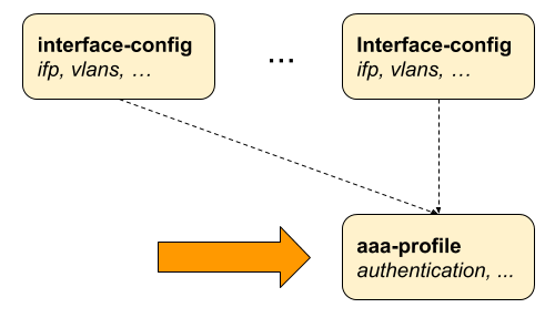
2.2.4. AAA Profile Configuration
Table: global.access.aaa.profile.config
Subscriber management requires the mandatory configuration of an Authentication, Authorization, and Accounting (AAA) profile.
The way that the AAA profile configuration relates to all subscriber management configuration tasks are shown in the picture below.
2.2.4.1. Configuring the AAA Profile
supervisor@switch: cfg> set access aaa-profile
  <profile-name>        Name of the AAA profile

supervisor@switch: cfg> set access aaa-profile aaa-example
  <cr>
  aaa-radius-profile    AAA RADIUS profile name
  accounting            Accounting options
  authentication        Authentication options
  idle-timeout          Idle timeout in seconds (0 == infinity)
  session-timeout       Session timeout in seconds (0 == infinity)
The following example shows a typical AAA profile for RADIUS authentication and accounting.
supervisor@switch: cfg> show config access aaa-profile aaa-radius
{
  "rtbrick-config:aaa-profile": {
    "profile-name": "aaa-radius",
    "session-timeout": 0,
    "idle-timeout": 0,
    "aaa-radius-profile": "radius-default",
    "authentication": {
      "order": "RADIUS"
    },
    "accounting": {
      "order": "RADIUS",
      "session-id-format": "DEFAULT",
      "ingress": {
        "accounting-source": "POLICER"
      },
      "egress": {
        "accounting-source": "CLASS",
        "class-byte-adjustment-value": 16
      }
    }
  }
}
| Attribute | Description |
|---|---|
session-timeout |
The session timeout specifies the maximum uptime in seconds until a subscriber is terminated. The value 0 means infinity. Default: 0 Range: 0 - 4294967295 |
idle-timeout |
The idle timeout specifies the time in seconds until a subscriber is terminated if no traffic is forwarded, based on outgoing logical interface statistics of the subscriber IFL. Those statistics do not include control traffic. The subscriber is not considered idle as long as egress traffic is detected. The idle timeout is not limited but should be set to at least double the time of the logical interface statistics counter update interval (between 5 to 30 seconds). The value 0 means infinity. Default: 0 Range: 0 - 4294967295 |
aaa-radius-profile |
The RADIUS profile (RADIUS Profile Configuration) which is used if RADIUS authentication or accounting is enabled. |
2.2.4.2. Configuring Authentication
RBFS supports the authentication methods NONE, LOCAL, DOMAIN, and RADIUS. The option
NONE disables authentication by accepting all credentials. The authentication method
LOCAL authenticates the subscriber based on locally defined user profiles
(User Profile Configuration). The method DOMAIN works similarly to LOCAL, but except for the whole username, only the domain part separated by a configurable domain delimiter (default @)is
used like rtbrick.com for user user@rtbrick.com. The authentication method RADIUS
authenticates the subscriber remotely by sending an authentication request to the defined
RADIUS servers.
|
|
The authentication method DOMAIN is currently not supported! |
Some methods can also be combined together. With LOCAL_RADIUS the subscriber is first authenticated locally and secondly via RADIUS if no matching local user is found. The subscriber is immediately rejected without requesting RADIUS servers if a local user is found, but the password does not match. The behavior is similar for RADIUS_LOCAL where the subscriber is immediately disconnected if the authentication request is rejected by RADIUS. In this case, local authentication is used as the fallback if no response is received (timeout) from any RADIUS server configured.
supervisor@switch: cfg> set config access aaa-profile aaa-default authentication
  <cr>
  delimiter             Delimiter string
  order                 Authentication order
| Attribute | Description | ||
|---|---|---|---|
order |
This option defines the order of authentication methods. Default: NONE Values: LOCAL, LOCAL_RADIUS, RADIUS, RADIUS_LOCAL |
||
delimiter |
This option defines the delimiter for domain authentication. Default: @
|
2.2.4.3. Configuring Accounting
Subscriber accounting refers to the process of measuring and recording the time and data usage of an corresponding subscriber. This includes the session time, called time accounting, and the number of packets and bytes transmitted or received called volume accounting.
Subscriber volume accounting works in both directions, but ingress and egress direction can be configured independently.
|
|
Today RBFS supports the accounting method RADIUS only! |
supervisor@switch: cfg> set config access aaa-profile aaa-default accounting
  <cr>
  egress                Egress volume accounting options
  ingress               Ingress volume accounting options
  interim-interval      Accounting interim interval in seconds (0 == disabled)
  order                 Accounting order
  session-id-format     Accounting-Session-Id format
| Attribute | Description | ||||||||||||||
|---|---|---|---|---|---|---|---|---|---|---|---|---|---|---|---|
order |
This option defines the order of accounting methods. Default: NONE |
||||||||||||||
interim-interval |
The interim interval specifies the time between interim accounting requests in seconds where 0 means disabled. Default: 0 Range: 0 - 4294967295 |
||||||||||||||
session-id-format |
The format of the Accounting-Session-Id (RADIUS attribute 44).
Default: DEFAULT Values: BRIEF, EXTENSIVE
|
2.2.4.4. Configuring Accounting Adjustments
The accounting adjustment feature enables basic counter modifications for the configured accounting method, such as RADIUS accounting. This configuration is necessary to normalize counters across different platforms in each direction. On Broadcom Q2C and Q2A based platforms, packets are counted in the size they enter the switch. Without adjustment, egress accounting would count downstream traffic as received from the core, complete with MPLS labels, while ingress accounting typically includes VLAN headers and/or PPPoE headers.
This counter adjustment aims to normalize counters with diverse encapsulations (double-tagged, untagged, etc.), potentially aligning to L3 counters (IP header and payload) as an example, or exclusively adapting egress traffic to match the outgoing packet encapsulation. The possibility for seperate adjustment configurations per direction allows parity in the counters for both ingress and egress.
Within RBFS, there are two configurations available for this purpose: the byte adjustment value and the factor, with the latter rarely needed. The byte adjustment value accommodates both positive and negative values, like -20.0 or 20.0. Any provided decimal digits in the adjustment values are ignored (e.g. 20.2 becomes 20.0). The byte adjustment factors accept positive values and utilize only the first two decimal places, such as 0.98 (-2%) or 1.02 (+2%).
2.2.4.4.1. Ingress Accounting
Subscriber ingress accounting refers to the process of measuring and recording the data usage or traffic that enters a subscriber interface (upstream).
supervisor@switch: cfg> set config access aaa-profile aaa-default accounting ingress
  <cr>
  accounting-source               Source of session ingress counter
  byte-adjustment-factor          Adjust ingress LIF counters by factor
  byte-adjustment-value           Adjust ingress LIF counters by N bytes per packet
  policer-byte-adjustment-factor  Adjust ingress policer counters by factor
  policer-byte-adjustment-value   Adjust ingress policer counters by N bytes per packet
| Attribute | Description |
|---|---|
accounting-source |
This option provides control over the counters used for subscriber ingress accounting when RADIUS accounting is enabled. The counters in question are the RADIUS attributes Acct-Input-Packets (47), Acct-Input-Octets (42), and Acct-Input-Gigawords (52). By default, the policer statistics (POLICER) are utilized, which represent the total traffic accepted across all policer levels (1-4). However, ingress control traffic is subject to a separate control plane policer and is therefore not included in the session policer statistics. Consequently, policers are necessary if session accounting is required. Alternatively, the logical interface (LIF) statistics can be employed, encompassing all received traffic, including control traffic and traffic dropped by the ingress policer. It is important to note that this option may not be available on all platforms. Default: POLICER Values: POLICER, LIF |
byte-adjustment-value |
Adjust ingress LIF counters by +/- N bytes per packet. Default: 0.00 Range: -32 - 32 |
byte-adjustment-factor |
Adjust ingress LIF counters by a factor (executed after adjustment value). Default: 1.00 Range: 0.00 - 2.00 |
policer-byte-adjustment-value |
Adjust ingress POLICER counters by +/- N bytes per packet. Default: 0.00 Range: -32 - 32 |
policer-byte-adjustment-factor |
Adjust ingress POLICER counters by factor (executed after adjustment value). Default: 1.00 Range: 0.00 - 2.00 |
2.2.4.4.2. Egress Accounting
Subscriber egress accounting refers to the process of measuring and recording the data usage or traffic that is sent from a subscriber interface (downstram).
supervisor@switch: cfg> set config access aaa-profile aaa-default accounting egress
  <cr>
  accounting-source             Source of session egress counter
  byte-adjustment-factor        Adjust egress LIF counters by a factor
  byte-adjustment-value         Adjust egress LIF counters by N bytes per packet
  class-byte-adjustment-factor  Adjust egress class counters by a factor
  class-byte-adjustment-value   Adjust egress class counters by N bytes per packet
| Attribute | Description |
|---|---|
accounting-source |
This option provides control over the counters used for egress session accounting when RADIUS accounting is enabled. The counters in question are the RADIUS attributes Acct-Output-Packets (48), Acct-Output-Octets (43), and Acct-Output-Gigawords (53). By default, the class statistics (CLASS) are utilized, which represent the total traffic accepted across all queues. However, the egress control traffic is sent directly to the IFP and is therefore not included in the session class statistics. Consequently, QoS is necessary if session accounting is required. As an alternative, the logical interface (LIF) statistics can be utilized, which cover all sent traffic, excluding control traffic. However, it is important to be aware that this option might not be accessible on all platforms. Default: CLASS Values: CLASS, LIF |
byte-adjustment-value |
Adjust egress LIF counters by +/- N bytes per packet. Default: 0.00 Range: -32 - 32 |
byte-adjustment-factor |
Adjust egress LIF counters by a factor (executed after adjustment value). Default: 1.00 Range: 0.00 - 2.00 |
class-byte-adjustment-value |
Adjust egress CLASS (queue) counters by +/- N bytes per packet. Default: 0.00 Range: -32 - 32 |
class-byte-adjustment-factor |
Adjust egress CLASS (queue) counters by factor (executed after adjustment value). Default: 1.00 Range: 0.00 - 2.00 |
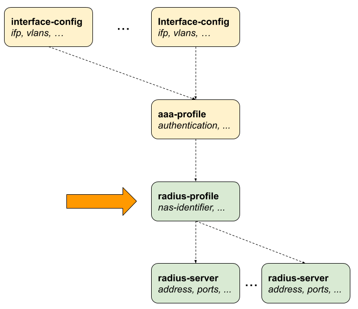
2.2.5. RADIUS Profile Configuration
Subscriber management allows the configuration of a RADIUS profile which is mandatory if RADIUS is used for authentication or accounting.
The way that the RADIUS profile configuration relates to all subscriber management configuration tasks is shown in the picture below.
2.2.5.1. Configuring the RADIUS Profile
supervisor@switch: cfg> set config access radius-profile
  <profile-name>        Name of the RADIUS profile

supervisor@switch: cfg> set config access radius-profile radius-default
  <cr>
  accounting            RADIUS accounting options
  authentication        RADIUS authentication options
  nas-identifier        NAS identifier
  nas-ip-address        NAS IP address (IPv4 Address)
  nas-port-format       NAS-Port format
  nas-port-type         NAS-Port type
The following example shows a typical RADIUS profile for authentication and accounting.
supervisor@switch: cfg> show config access radius-profile radius-default
{
  "rtbrick-config:radius-profile": {
    "profile-name": "radius-default",
    "nas-identifier": "BNG",
    "nas-port-type": "Ethernet",
    "authentication": {
      "radius-server-profile-name": [
        "radius-server-1",
        "radius-server-2"
        ]
    },
    "accounting": {
      "radius-server-profile-name": [
        "radius-server-1",
        "radius-server-2"
        ],
      "stop-on-reject": "true",
      "stop-on-failure": "true",
      "accounting-on-off": "true",
      "accounting-on-wait": "true",
      "accounting-backup": "true",
      "accounting-backup-max": 86400
    }
  }
}
| Attribute | Description | |||||||||
|---|---|---|---|---|---|---|---|---|---|---|
nas-identifier |
Set the value for the RADIUS attribute NAS-Identifier (32). Default: system hostname |
|||||||||
nas-ip-address |
Set the value for RADIUS attribute NAS-IP-Address (4). Default: source IPv4 address |
|||||||||
nas-port-type |
Set the value for RADIUS attribute NAS-Port-Type (61). Default: Ethernet |
|||||||||
nas-port-format |
Set the format of the 32-bit RADIUS attribute NAS-Port (5).
|
2.2.5.2. Configuring Authentication
supervisor@switch: cfg> set config access radius-profile radius-default authentication
  <cr>
  algorithm-type              Authentication redundancy algorithm
  radius-server-profile-name  RADIUS server profile name
| Attribute | Description |
|---|---|
radius-server-profile-name |
List of RADIUS servers used for authentication. |
algorithm-type |
Authentication server selection algorithm as described in RADIUS Redundancy. Default: DIRECT Values: DIRECT, ROUND-ROBIN |
2.2.5.3. Configuring Accounting
supervisor@switch: cfg> set config access radius-profile radius-default accounting
  <cr>
  accounting-backup           Enable backup accounting
  accounting-backup-max       Max backup accounting hold time in seconds
  accounting-on-off           Enable accounting on/off
  accounting-on-wait          Wait for an accounting-on response before sending authentication requests
  algorithm-type              Accounting redundancy algorithm
  radius-server-profile-name  RADIUS server profile name
  stop-on-failure             Send accounting-stop on failure
  stop-on-reject              Send accounting-stop on authentication reject
| Attribute | Description |
|---|---|
radius-server-profile-name |
List of RADIUS servers used for accounting. |
algorithm-type |
Accounting server selection algorithm as described in RADIUS Redundancy. Default: DIRECT Values: DIRECT, ROUND-ROBIN |
stop-on-failure |
Sent RADIUS accounting request stop in case of failure after authentication was accepted. Default: false |
stop-on-reject |
Sent RADIUS accounting request stop in case of authentication is rejected. Default: false |
accounting-on-off |
Enable RADIUS Accounting-On/Off messages as described in RADIUS Accounting. Default: false |
accounting-on-wait |
This option prevents any new subscriber until the accounting hast started meaning that the Accounting-On response was received. Default: false |
accounting-backup |
RADIUS accounting requests are often used for billing and, therefore should be able to store and retry over a longer period (common up to 24 hours or more) which can be optionally enabled here. Default: false |
accounting-backup-max |
This option defines maximum backup accounting hold time in seconds if accounting backup is enabled. Default: 3600 Range: 1 - 4294967295 |
2.2.6. RADIUS Server Configuration
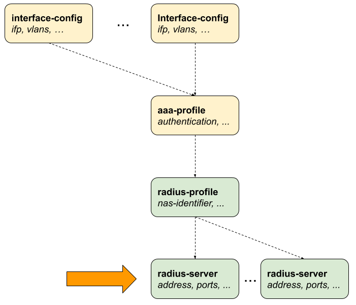
Successful subscriber management AAA methods are often supplied by a RADIUS server, although there are cases where other forms of AAA, including local methods independent of network availability, are appropriate.
RADIUS server configuration is a dependent step in subscriber management configuration. In other words, if you configure an optional RADIUS profile for AAA, then you must configure a RADIUS server to go along with it. So, RADIUS server configuration is dependent on RADIUS profile configuration.
The way that the RADIUS server configuration relates to all subscriber management configuration tasks is shown in the picture below.
2.2.6.1. Configuring the RADIUS Server
supervisor@switch: cfg> set config access radius-server
  <server-name>         Name of the RADIUS server

supervisor@switch: cfg> set config access radius-server radius-server-1
  <cr>
  accounting             RADIUS accounting mode
  address                RADIUS server address
  authentication         RADIUS authentication mode
  coa                    RADIUS Change-of-Authorization (CoA) mode
  rate                   Maximum RADIUS requests per/second
  routing-instance       Instance name
  secret-encrypted-text  RADIUS secret in encrypted text
  secret-plain-text      RADIUS secret in plain text
  source-address         Source address used for RADIUS packets
The following example shows a typical …
supervisor@switch: cfg> show config access radius-server radius-server-1
{
  "rtbrick-config:radius-server": {
    "server-name": "radius-server-1",
    "address": "198.51.100.101",
    "source-address": "198.51.100.200",
    "secret-encrypted-text": "$21e4946e31b406de98b3077aef03ed5a7",
    "authentication": {
      "enable": "true"
    },
    "accounting": {
      "enable": "true"
    },
    "coa": {
      "enable": "true"
    }
  }
}
| Attribute | Description |
|---|---|
address |
RADIUS server IPv4 address. Multiple RADIUS servers with the same IPv4 address are currently not supported, even if the instance or port is different.! |
source-address |
Local source IPv4 address. |
routing-instance |
The routing instance in which the RADIUS server is reachable. |
secret-encrypted-text secret-plain-text |
RADIUS secret, which can be provided as plaintext or already encrypted text. |
rate |
Maximum RADIUS requests per second. Default: 600 Range: 1 - 65535 |
2.2.6.2. Configuring Authentication
supervisor@switch: cfg> set access radius-server radius-server-1 authentication
  <cr>
  enable                Enable RADIUS authentication
  outstanding           Maximum number of outstanding authentication requests
  port                  RADIUS server authentication port
  retry                 Maximum retries for authentication request packets
  timeout               Authentication request timeout in seconds
| Attribute | Description |
|---|---|
enable |
Enable RADIUS authentication. Default: false |
port |
RADIUS authentication port. Default: 1812 Range: 1 - 65535 |
retry |
This option specifies the number of authentication retries before declaring this server as unreachable for authentication. After reaching the limit, the client begins to send requests to other RADIUS servers and rejects the request after receiving the end of the list. Default: 3 Range: 1 - 255 |
timeout |
Authentication request timeout in seconds. Default: 5 Range: 1 - 65535 |
outstanding |
This option specifies the maximum number of outstanding authentication requests for this RADIUS server. A request is counted as outstanding if sent out but the response is not received. Default: 100 Range: 1 - 65535 |
2.2.6.3. Configuring Accounting
supervisor@switch: cfg> set access radius-server radius-server-1 accounting
  <cr>
  enable                Enable RADIUS accounting
  outstanding           Maximum number of outstanding accounting requests
  port                  RADIUS server accounting port
  retry                 Maximum retries for accounting request packets
  timeout               Accounting request timeout in seconds
| Attribute | Description |
|---|---|
enable |
Enable RADIUS accounting. Default: false |
port |
RADIUS authentication port. Default: 1813 Range: 1 - 65535 |
retry |
This option specifies the number of accounting retries before declaring this server as unreachable for accounting. After reaching the limit, the client begins to send requests to other RADIUS servers. Default: 10 Range: 1 - 255 |
timeout |
Authentication request timeout in seconds. Default: 30 Range: 1 - 65535 |
outstanding |
This option specifies the maximum number of outstanding accounting requests for this RADIUS server. A request is counted as outstanding if sent out, but the response is not received. Default: 100 Range: 1 - 65535 |
2.2.6.4. Configuring Change-of-Authorization (CoA)
supervisor@switch: cfg> set access radius-server radius-server-1 coa
  <cr>
  enable                Enable Change-of-Authorization (CoA)
  port                  Local RADIUS CoA port
| Attribute | Description |
|---|---|
enable |
Enable receiving of RADIUS CoA requests from this server. Default: false |
port |
RADIUS CoA port. Default: 3799 Range: 1 - 65535 |
2.2.7. Service Profile Configuration
Service profile configuration is an optional step in subscriber management configuration which allows to assign QoS or IGMP configurations to a subscriber.
The way that the service profile configuration relates to all subscriber management configuration tasks is shown in the picture below.
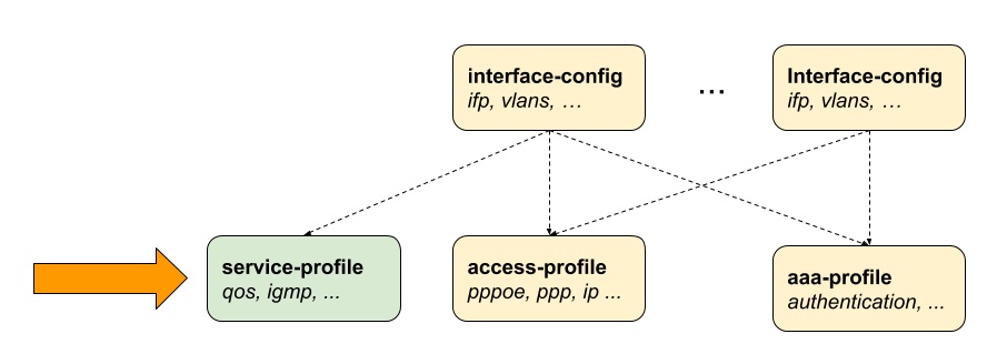
2.2.7.1. Configuring the Service Profile
supervisor@switch: cfg> set access service-profile
  <profile-name>        Name of the service profile

supervisor@switch: cfg> set access service-profile iptv
  <cr>
  igmp                  IGMP related attributes
  qos                   QoS related attributes
The following example shows a typical service profile for subscribers with IPTV (multicast) services.
supervisor@switch: cfg> show config access service-profile iptv
{
  "rtbrick-config:service-profile": {
    "profile-name": "iptv",
    "qos": {
      "profile": "iptv-qos-xl"
    },
    "igmp": {
      "enable": "true",
      "profile": "iptv-basic",
      "version": "IGMPv3",
      "max-members": 10
    }
  }
}
2.2.7.2. Configuring QoS
supervisor@switch: cfg> set access service-profile iptv qos
  <cr>
  parent-scheduler      QoS parent scheduler
  profile               QoS profile
| Attribute | Description | ||
|---|---|---|---|
parent-scheduler |
This options defines the parent scheduler element of the scheduler-map which is assigned to the subscriber. If not present, the scheduler-map will be directly bound to the local IFP where the session is established. This attribute can be only set once and never be changed without disconnect of the session. The parent scheduler can be also set via RADIUS which has priority over the one defined here.
|
||
profile |
This option assigns a QoS configuration profile to the subscriber. The QoS profile can be also set via RADIUS which has priority over the one defined here. |
2.2.7.3. Configuring IGMP
supervisor@switch: cfg> set access service-profile iptv igmp
  <cr>
  enable                Enable IGMP service
  max-members           Maximum IGMP membership per subscriber
  profile               IGMP profile
  version               IGMP version
| Attribute | Description |
|---|---|
enable |
This attribute dynamically enables or disables IGMP for a subscriber. Default: false |
max-members |
This attribute limits the number of parallel multicast channels (maximum IGMP membership) for a subscriber. Default: 1 Range: 1 - 4294967295 |
profile |
This attribute specifies the IGMP profile to be associated with the subscriber. |
version |
This attribute can specify the version of IGMP for a subscriber. Default: V3 Values: V1, V2, V3 |
2.2.8. L2TP Profile Configuration
The Layer 2 Tunnel Protocol (L2TPv2) profile configuration is an optional step in subscriber management configuration which is mandatory to enable L2TP tunneling.
The picture below illustrates how all subscriber management configuration tasks are related to L2TP profile configuration.
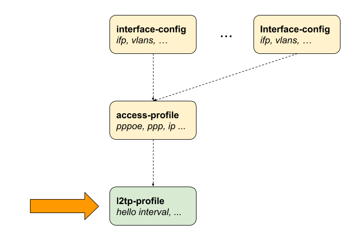
2.2.8.1. Configuring the L2TP Profile
supervisor@switch: cfg> set access l2tp-profile
  <profile-name>        Name of the L2TP profile

supervisor@switch: cfg> set access l2tp-profile l2tp-default
  <cr>
  client-ipv4                Default value for L2TP tunnel client IPv4 address
  client-name                Default value for L2TP tunnel client name
  connect-speed-update       Enable L2TP Connect-Speed-Update-Notification (CSUN)
  dead-timeout-interval      L2TP tunnel dead timeout interval in seconds
  hello-interval             L2TP tunnel hello interval in seconds
  hide-authentication        Hide L2TP tunnel authentication
  idle-timeout-interval      L2TP tunnel idle timeout interval in seconds
  inactive-timeout-interval  L2TP tunnel inactive timeout interval in seconds
  instance                   Instance name
  pon-access-line-version    PON Access Line Information Version
  pool-name                  L2TP tunnel pool name
  receive-window             L2TP tunnel receive window
  request-retries            L2TP session request retries
  request-timeout-interval   L2TP session request timeout interval in seconds
  retransmit-interval        L2TP tunnel retransmission interval in seconds
  selection-algorithm        L2TP tunnel selection algorithm
  service-label              MPLS service label
  session-limit              L2TP tunnel session limit
The following example shows a typical L2TPv2 LAC configuration profile.
supervisor@switch: cfg> show config access l2tp-profile l2tp-default
{
  "rtbrick-config:l2tp-profile": {
    "profile-name": "l2tp-default",
    "session-limit": 4000,
    "hello-interval": 60,
    "client-name": "BNG",
    "client-ipv4": "198.51.100.200",
    "hide-authentication": true
    "service-label": 1234
  }
}
| Attribute | Description | ||
|---|---|---|---|
client-ipv4 |
This is the default value for the local L2TP tunnel client (LAC) IPv4 address if not explicitly provided for the tunnel via L2TP pool or RADIUS. |
||
client-name |
This is the default value for the local L2TP tunnel client (LAC) hostname if not explicitly provided for the tunnel via L2TP pool or RADIUS. Default: system hostname |
||
instance |
The routing instance in which the L2TP endpoint (LNS) is reachable. Default: default |
||
service-label |
The service label must be defined to support L2TP over MPLS
(Configuring L2TP over MPLS). |
||
selection-algorithm |
This defines how to select a tunnel from a pool of available LNS servers as described in L2TP Tunnel Selection. The RANDOM algorithm selects the tunnel randomly, whereas BALANCED selects the least filled tunnel based on the number of sessions. Default:: BALANCED Values: BALANCED, RANDOM |
||
session-limit |
This is the default tunnel session limit if not further specified. Tunnels with session limit reached are not considered for further sessions. Default: 64000 Range: 1 - 65535 |
||
pool-name |
This attribute allows to assign a default L2TP tunnel pool (L2TP Tunnel Pool Configuration) which can be overwritten by user defined pool names from local user profiles (User Profile Configuration) or received via RADIUS attribute RtBrick-L2TP-Pool (VSA 26-50058-40). |
||
hello-interval |
L2TP tunnel hello interval in seconds where 0 means disabled. The HELLO keep alive messages are part of the L2TP control channel (L2TP Control Channel) and only send if there is no other message send if queue is empty and no other message sends during the hello interval. Default: 30 Range: 0 - 86400 |
||
idle-timeout-interval |
This interval defines the maximum time in seconds to keep a tunnel without sessions established. The session will remain forever if this value is set to 0. Default: 600 Range: 0 - 4294966 |
||
dead-timeout-interval |
This interval defines the time in seconds to keep an unreachable tunnel in a DEAD state. After interval expiration the tunnel changes back to DOWN state to be available for new sessions. Default: 300 Range: 1 - 4294966 |
||
inactive-timeout-interval |
This interval defines the time in seconds to keep an inactive tunnel before removal. This interval is reset with every new session request which considers this tunnel as a potential candidate. Default: 900 Range: 1 - 4294966 |
||
receive-window |
This value specifies the receive window size being offered to the remote peer trough Receive Window Size AVP (10) in SCCRQ, SCCRP. Suppose advertising a receive window size of 8 in the SCCRQ or SCCRP messages. The remote peer is now allowed to have up to 8 outstanding control messages. Once eight have been sent; it must wait for an acknowledgment that advances the window before sending new control messages. Default: 8 Range: 1 - 256 |
||
request-retries |
This value is explained together with request-timeout-interval. Default: 5 Range: 1 - 600 |
||
request-timeout-interval |
This interval multiplied with the request-retries defines the maximum time in seconds to wait for the selected tunnel to become established before selecting another tunnel from the list. Default: 1 Range: 1 - 30
|
||
retransmit-interval |
This value specifies the retransmission interval in seconds. Each subsequent retransmission of a message employ an exponential backoff interval. Thus, if the first retransmission occurred after 1 second; the next retransmission occurred after 2 seconds had elapsed, then 4 seconds, 8 seconds, 16 seconds, 32 seconds, and finally 64 seconds. This maximum value is reached after a maximum of 6 retransmissions resulting in max 64 seconds for a retransmit interval of 1, 128 seconds for 2, etc. Default: 1 Range: 1 - 30 |
||
hide-authentication |
If enabled, the L2TP proxy authentication response AVP will be hidden if authentication type is PAP to not transmit the password in clear text. Default: false |
||
pon-access-line-version |
Adding additional PON attributes to the L2TP access line information (L2TP Access Line Information (RFC5515)) as defined in draft-lihawi-ancp-protocol-access-extension which can be optionally enabled using this configuration attribute.
The value DRAFT-LIHAWI-00 enables PON attributes based on the definition in draft-lihawi-ancp-protocol-access-extension-00 whereas DRAFT-LIHAWI-04 uses draft-lihawi-ancp-protocol-access-extension-04. Default:: DISABLED Values: DRAFT-LIHAWI-00, DRAFT-LIHAWI-04 |
||
connect-speed-update |
Enable L2TP Connect-Speed-Update-Notification (CSUN) requests as defined in RFC5515 (Connect-Speed-Update-Notification (CSUN)). CSUN is an L2TP control message sent by the LAC to the LNS to provide transmit and receive connection speed updates for one or more sessions which is disabled per default and can be enabled using this configuration. Default: false |
2.2.8.2. Configuring L2TP over MPLS
L2TP over MPLS requires a dedicated L2TP service label which needs to be configured manually.
Following an example L2TP configuration with L2TP service label.
set access l2tp-profile l2tp-default service-label 1234
Advertising this label via BGP must be configured manually as shown in the example below. The exact policy configuration depends on the actual network and existing policy concept.
supervisor@switch: cfg> show config policy
{
    "rtbrick-config:policy": {
      "statement": [
        {
          "name": "L2TP_MPLS",
          "ordinal": [
            {
              "ordinal": 1,
              "match": {
                "rule": [
                  {
                    "rule": 1,
                    "type": "ipv4-prefix",
                    "value-type": "discrete",
                    "match-type": "exact",
                    "value": "198.51.100.200/24"
                  }
                ]
              },
              "action": {
                "rule": [
                  {
                    "rule": 1,
                    "type": "label",
                    "operation": "overwrite",
                    "value": "label:1337,bos:1"
                  }
                ]
              }
            },
            {
              "ordinal": 2,
              "action": {
                "rule": [
                  {
                    "rule": 1,
                    "operation": "return-permit"
                  }
                ]
              }
            }
          ]
        }
      ]
    }
  }


supervisor@switch: cfg> show config instance internet
{
  "rtbrick-config:instance": {
    "name": "internet",
    "address-family": [
      {
        "afi": "ipv4",
        "safi": "unicast",
        "policy": {
          "export": "L2TP_MPLS"
        }
      }
    ]
  }
}
2.2.9. L2TP Tunnel Pool Configuration
The Layer 2 Tunnel Protocol (L2TPv2) pool configuration is an optional step in subscriber management configuration which allows to define local sets of possible L2TP LNS server endpoints.
2.2.9.1. Configuring the L2TP Tunnel Pool
supervisor@switch: cfg> set access l2tp-pool
  <pool-name>           Name of the L2TP pool

supervisor@switch: cfg> set access l2tp-pool lns-servers
  <client-name>         L2TP client (LAC) name

supervisor@switch: cfg> set access l2tp-pool lns-servers BNG
  <server-name>         L2TP server (LNS) name

supervisor@switch: cfg> set access l2tp-pool lns-servers BNG LNS
  <cr>
  client-ipv4            L2TP client (LAC) IPv4
  preference             Preference
  secret-encrypted-text  Shared secret in encrypted text
  secret-plain-text      Shared secret in plain text
  server-ipv4            L2PTP server (LNS) IPv4
  session-limit          Session limit
The following example shows a local pool with two LNS severs.
supervisor@switch: cfg> show config access
{
  "rtbrick-config:access": {
    "l2tp-pool": [
      {
        "pool-name": "lns-pool-example",
        "client-name": "BNG",
        "server-name": "LNS1",
        "client-ipv4": "198.51.100.200",
        "server-ipv4": "198.51.100.219",
        "secret-encrypted-text": "$21e4946e31b406de98b3077aef03ed5a7",
        "preference": 1000,
        "session-limit": 1000
      },
      {
        "pool-name": "lns-pool-example",
        "client-name": "BNG",
        "server-name": "LNS2",
        "client-ipv4": "198.51.100.200",
        "server-ipv4": "198.51.100.220",
        "secret-encrypted-text": "$21e4946e31b406de98b3077aef03ed5a7",
        "preference": 1000,
        "session-limit": 1000
      }
    ]
  }
}
| Attribute | Description |
|---|---|
client-name |
Local L2TP tunnel client (LAC) hostname. |
server-name |
Remote L2TP tunnel server (LNS) hostname. |
client-ipv4 |
Local L2TP tunnel client (LAC) IPv4 address. |
server-ipv4 |
Remote L2TP tunnel server (LNS) IPv4 address. |
secret-encrypted-text secret-plain-text |
L2TP tunnel secret, which can be provided as plaintext or already encrypted text. |
preference |
L2TP tunnel preference where the lowest value has the highest priority. Default: 0 Range: 1 - 65535 |
session-limit |
Tunnels with a session limit reached are not considered for further sessions. This limit has precedence over the default session limit specified in the l2tp-profile. Default: 64000 Range: 1 - 65535 |
2.2.10. User Profile Configuration
Subscribers are typically authenticated through remote servers like RADIUS. RBFS additionally offers the capability to authenticate these sessions by comparing them with user profiles defined locally within the system.
2.2.10.1. Configuring the User Profile
supervisor@switch: cfg> set access user-profile
  <user-name>           Username

supervisor@switch: cfg> set access user-profile user@rtbrick.com
  <cr>
  l2tp-pool-name           L2TP pool name
  password-encrypted-text  Secret/password in encrypted text
  password-plain-text      Secret/password in plain text
  tunnel-type              Tunnel type
The following example shows a typical ….
supervisor@switch: cfg> show config access user-profile user@rtbrick.com
{
  "rtbrick-config:user-profile": {
    "user-name": "user@rtbrick.com",
    "password-encrypted-text": "$243a1341f44f54888cdd385b9f40513f1",
    "tunnel-type": "PPPoE"
  }
}
| Attribute | Description |
|---|---|
user-name |
Username of the subscriber. |
password-encrypted-text password-plain-text |
User password which can be provided as plaintext or already encrypted text. |
tunnel-type |
Subscriber tunnel type. Default: PPPoE Values: PPPoE, L2TP |
l2tp-pool-name |
Assign a local configured L2TP tunnel pool. |
2.2.11. Address Pool Configuration
The way that the address pool configuration relates to all subscriber management configuration tasks is shown in the picture below.
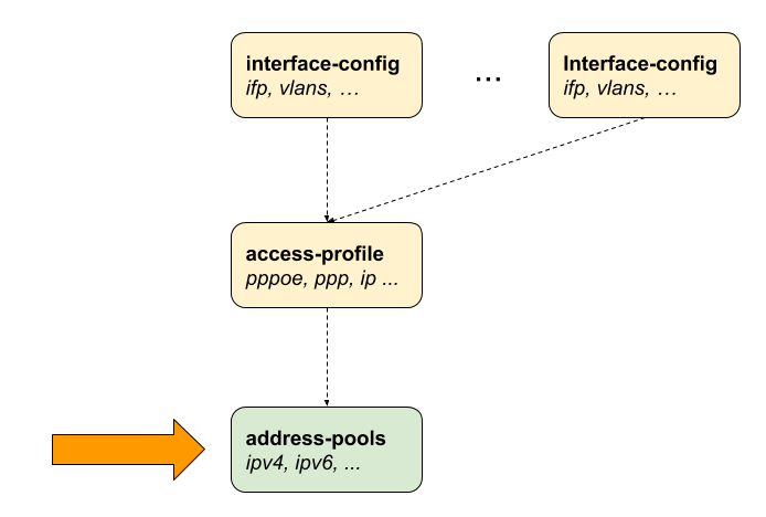
2.2.11.1. Configuring the Address Pool
   set access pool
  <pool-name>           Name of the address pool

supervisor@switch: cfg> set access pool ipv4-local
  <cr>
  ipv4-address          IPv4 address pool configuration
  ipv6-prefix           IPv6 prefix pool configuration
  next-pool-name        Name of the next address pool to be used if full
The following example shows typical IPv4 address and IPv6 prefix pools.
supervisor@switch: cfg> show config access
{
  "rtbrick-config:access": {
    "pool": [
      {
        "pool-name": "ipv4-local",
        "ipv4-address": {
          "low": "198.51.100.76",
          "high": "198.51.100.117"
        }
      },
      {
        "pool-name": "ipv6-local",
        "ipv6-prefix": {
          "low": "2001:db8:0:79::/32",
          "high": "2001:db8:0:139::/32"
        }
      },
      {
        "pool-name": "ipv6pd-local",
        "ipv6-prefix": {
          "low": "2001:db8:0:1::/32",
          "high": "2001:db8:0:100::/32"
        }
      }
    ],
  }
}
The management of address pools in RBFS offers the flexibility to remove or modify them without causing any disruptions to existing subscribers. This means that even after an address pool has been deleted, the subscribers who were assigned addresses from that pool can still retain and utilize those addresses.
To illustrate, let’s consider a scenario where a subscriber has been allocated an IP address from a specific pool, and later on, that pool is deleted. Despite the pool’s removal, the subscriber can continue using the assigned IP address until their session is terminated. Operators are responsible for ensuring that the address pool is not allocated elsewhere until it’s finally released.
RBFS supports an optional feature known as duplicate address detection. This functionality aims to prevent sessions from logging in if they attempt to use an already-used address. However, it’s important to note that this safeguard doesn’t apply if the address pool is moved to a different BNG. In such cases, duplicate address detection might not work as anticipated, emphasizing the need for careful management and planning when migrating address pools across different BNGs.
2.2.11.2. Configuring IPv4 Address Pools
supervisor@switch: cfg> set access pool ipv4-local ipv4-address
  <cr>
  high                  Highest IPv4 address
  low                   Lowest IPv4 address
  subnet-mask           Subnet mask
| Attribute | Description |
|---|---|
high |
Highest IPv4 address. |
low |
Lowest IPv4 address. |
subnet-mask |
subnet mask allocated to the subscriber. |
2.2.11.3. Configuring IPv6 Prefix Pools
supervisor@switch: cfg> set access pool ipv6-local ipv6-prefix
  <cr>
  high                  Highest IPv6 prefix
  low                   Lowest IPv6 prefix
| Attribute | Description |
|---|---|
high |
Highest IPv6 prefix. |
low |
Lowest IPv6 prefix. |
|
|
IPv6 prefixes must be at least /64 or larger (/56, /48, …) or /128. |
2.2.11.4. Configuring Linked Pools
Multiple address pools can be linked together using the next-pool-name attribute
to form a larger pool of discontinuous ranges.
A -→ B -→ C -→ D
supervisor@switch: cfg> set access pool pool-A next-pool pool-B
supervisor@switch: cfg> set access pool pool-B next-pool pool-C
supervisor@switch: cfg> set access pool pool-C next-pool pool-D
The actual address pool assigned to a subscriber from the access configuration profile or RADIUS defines the start pool, which could be any pool in the chain. If this pool is already full, the next pool is requested, which repeats until a free pool is found or the end of the chain is reached. RBFS also stops automatically as soon as one pool of the chain was entered twice (loop protection).
This chain can also be closed to a loop to ensure that all pools of a chain are considered if one pool from the middle of the chain is allocated.
A -→ B -→ C -→ D -→ A
supervisor@switch: cfg> set access pool pool-A next-pool pool-B
supervisor@switch: cfg> set access pool pool-B next-pool pool-C
supervisor@switch: cfg> set access pool pool-C next-pool pool-D
supervisor@switch: cfg> set access pool pool-D next-pool pool-A
2.2.12. Control Plane Outbound Marking Configuration
The process of marking all outbound control plane packets
is established through the configuration settings found within
the forwarding-options, which are illustrated in the
following example. This configuration enables effective
management and control over the attributes associated with these
packets as they traverse the network. By employing these settings,
network operators can ensure that control plane traffic is
appropriately identified and treated according to specified criteria,
contributing to an optimized and well-orchestrated network environment.
supervisor@switch: cfg> show config forwarding-options
{
    "rtbrick-config:forwarding-options": {
      "class-of-service": {
        "control-plane-qos": {
          "outbound-marking": {
            "protocol": [
              {
                "protocol": "l2tpv2",
                "remark-type": "tos",
                "codepoint": 64
              },
              {
                "protocol": "ppp",
                "remark-type": "p-bit",
                "codepoint": 6
              },
              {
                "protocol": "radius",
                "remark-type": "tos",
                "codepoint": 64
              }
            ]
          }
        }
      }
    }
  }
2.3. Configuration Examples
2.3.1. PPPoE
The following example shows a PPPoE configuration for VLAN mode 1:1 with IPv4 and IPv6 enabled, authenticated via RADIUS.
{
  "ietf-restconf:data": {
    "rtbrick-config:access": {
      "aaa-profile": [
        {
          "profile-name": "aaa-radius",
          "session-timeout": 0,
          "idle-timeout": 0,
          "aaa-radius-profile": "radius-default",
          "authentication": {
            "order": "RADIUS"
          },
          "accounting": {
            "order": "RADIUS",
          }
        }
      ],
      "radius-profile": [
        {
          "profile-name": "radius-default",
          "nas-identifier": "BNG",
          "nas-port-type": "Ethernet",
          "authentication": {
            "radius-server-profile-name": [
              "radius-server-1",
              "radius-server-2"
              ]
          },
          "accounting": {
            "radius-server-profile-name": [
              "radius-server-1",
              "radius-server-2"
              ],
            "stop-on-reject": "true",
            "stop-on-failure": "true",
            "accounting-on-off": "true",
            "accounting-on-wait": "true",
            "accounting-backup": "true",
            "accounting-backup-max": 86400
          }
        }
      ],
      "radius-server": [
        {
          "server-name": "radius-server-1",
          "address": "198.51.100.101",
          "source-address": "198.51.100.200",
          "secret-encrypted-text": "$21e4946e31b406de98b3077aef03ed5a7",
          "authentication": {
            "enable": "true"
          },
          "accounting": {
            "enable": "true"
          },
          "coa": {
            "enable": "true"
          }
        },
        {
          "server-name": "radius-server-2",
          "address": "198.51.100.102",
          "source-address": "198.51.100.200",
          "secret-encrypted-text": "$21e4946e31b406de98b3077aef03ed5a7",
          "authentication": {
            "enable": "true"
          },
          "accounting": {
            "enable": "true"
          },
          "coa": {
            "enable": "true"
          }
        }
      ],
      "access-profile": [
        {
          "profile-name": "pppoe-dual",
          "protocol": {
            "pppoe": {
              "enable": "true",
              "session-protection": {
                "enable": "true"
              },
              "vlan-priority": 6
            },
            "ppp": {
              "lcp": {
                "authentication-protocol": "PAP_CHAP",
                "echo-interval": 30,
                "echo-max-retransmit": 3,
                "echo-enable": "true"
              },
              "ipcp": {
                "enable": "true",
                "source-ifl": "lo-0/0/0/1"
              },
              "ip6cp": {
                "enable": "true"
              }
            },
            "ra": {
              "enable": "true",
              "interval": 60
            },
            "dhcpv6": {
              "enable": "true"
            },
            "l2tp": {
              "tunnel-profile": "l2tp-default"
            }
          },
          "address-family": {
            "ipv4": {
              "enable": "true",
              "primary-dns": "198.51.100.103",
              "secondary-dns": "198.51.100.104",
              "instance": "default"
            },
            "ipv6": {
              "enable": "true",
              "primary-dns": "2001:db8:0:100::",
              "secondary-dns": "2001:db8:0:104::",
              "instance": "default"
            }
          }
        }
      ],
      "interface": {
        "double-tagged": [
          {
            "interface-name": "ifl-0/0/1",
            "outer-vlan-min": 1,
            "outer-vlan-max": 4094,
            "inner-vlan-min": 7,
            "inner-vlan-max": 7,
            "access-type": "PPPoE",
            "access-profile-name": "pppoe-dual",
            "aaa-profile-name": "aaa-radius"
          }
        ]
      },
      "l2tp-profile": [
        {
          "profile-name": "l2tp-default",
          "session-limit": 4000,
          "client-name": "BNG",
          "client-ipv4": "198.51.100.200",
          "hide-authentication": true
        }
      ]
    },
    "rtbrick-config:interface": [
      {
        "name": "ifl-0/0/1",
        "description": "Access",
        "host-if": "eth0"
      },
      {
        "name": "ifl-0/0/2",
        "description": "Core",
        "host-if": "eth1",
        "unit": [
          {
            "unit-id": 1,
            "address": {
              "ipv4": [
                {
                  "prefix4": "198.51.100.33/24"
                }
              ],
              "ipv6": [
                {
                  "prefix6": "2001:db8:0:32::/32"
                }
              ]
            }
          }
        ]
      },
      {
        "name": "lo-0/0/0",
        "unit": [
          {
            "unit-id": 1,
            "address": {
              "ipv4": [
                {
                  "prefix4": "198.51.100.200/24"
                }
              ]
            }
          }
        ]
      }
    ]
  }
}
2.3.2. IPoE
The following example shows an IPoE configuration for VLAN mode 1:1 with IPv4 and IPv6 enabled, authenticated via RADIUS.
{
  "ietf-restconf:data": {
    "rtbrick-config:access": {
      "aaa-profile": [
        {
          "profile-name": "aaa-radius",
          "session-timeout": 0,
          "idle-timeout": 0,
          "aaa-radius-profile": "radius-default",
          "authentication": {
            "order": "RADIUS"
          },
          "accounting": {
            "order": "RADIUS",
          }
        }
      ],
      "radius-profile": [
        {
          "profile-name": "radius-default",
          "nas-identifier": "BNG",
          "nas-port-type": "Ethernet",
          "authentication": {
            "radius-server-profile-name": [
              "radius-server-1",
              "radius-server-2"
              ]
          },
          "accounting": {
            "radius-server-profile-name": [
              "radius-server-1",
              "radius-server-2"
              ],
            "stop-on-reject": "true",
            "stop-on-failure": "true",
            "accounting-on-off": "true",
            "accounting-on-wait": "true",
            "accounting-backup": "true",
            "accounting-backup-max": 86400
          }
        }
      ],
      "radius-server": [
        {
          "server-name": "radius-server-1",
          "address": "198.51.100.101",
          "source-address": "198.51.100.200",
          "secret-encrypted-text": "$21e4946e31b406de98b3077aef03ed5a7",
          "authentication": {
            "enable": "true"
          },
          "accounting": {
            "enable": "true"
          },
          "coa": {
            "enable": "true"
          }
        },
        {
          "server-name": "radius-server-2",
          "address": "198.51.100.102",
          "source-address": "198.51.100.200",
          "secret-encrypted-text": "$21e4946e31b406de98b3077aef03ed5a7",
          "authentication": {
            "enable": "true"
          },
          "accounting": {
            "enable": "true"
          },
          "coa": {
            "enable": "true"
          }
        }
      ],
      "access-profile": [
        {
          "profile-name": "ipoe-dual",
          "protocol": {
            "dhcp": {
              "enable": "true",
              "mode": "server"
            },
            "dhcpv6": {
              "enable": "true",
              "mode": "server"
            },
          },
          "address-family": {
            "ipv4": {
              "enable": "true",
              "pool-name":"ipoe",
              "primary-dns": "198.51.100.103",
              "secondary-dns": "198.51.100.104",
              "instance": "default"
            },
            "ipv6": {
              "enable": "true",
              "pool-name":"ipoe-ia-na",
              "prefix-delegation-pool-name":"ipoe-ia-pd",
              "primary-dns": "2001:db8:0:100::",
              "secondary-dns": "2001:db8:0:104::",
              "instance": "default"
            }
          }
        }
      ],
      "interface": {
        "double-tagged": [
          {
            "interface-name": "ifl-0/0/1",
            "outer-vlan-min": 1,
            "outer-vlan-max": 4094,
            "inner-vlan-min": 7,
            "inner-vlan-max": 7,
            "access-type": "IPoE",
            "access-profile-name": "ipoe-dual",
            "aaa-profile-name": "aaa-radius",
            "gateway-ifl": "lo-0/0/0/1"
          }
        ]
      },
      "pool": [
        {
          "pool-name": "ipoe",
          "ipv4-address": {
            "low": "10.0.0.1",
            "high": "10.0.255.255"
          }
        },
        {
          "pool-name": "ipoe-ia-na",
          "ipv6-prefix": {
            "low": "fc66::1/128",
            "high": "fc66::ffff/128"
          }
        },
        {
          "pool-name": "ipoe-ia-pd",
          "ipv6-prefix": {
            "low": "fc66:0:100::/56",
            "high": "fc66:0:1ff:ff00::/56"
          }
        }
      ],
    },
    "rtbrick-config:interface": [
      {
        "name": "ifl-0/0/1",
        "description": "Access",
        "host-if": "eth0"
      },
      {
        "name": "ifl-0/0/2",
        "description": "Core",
        "host-if": "eth1",
        "unit": [
          {
            "unit-id": 1,
            "address": {
              "ipv4": [
                {
                  "prefix4": "198.51.100.33/24"
                }
              ],
              "ipv6": [
                {
                  "prefix6": "2001:db8:0:6423::/32"
                }
              ]
            }
          }
        ]
      },
      {
        "name": "lo-0/0/0",
        "unit": [
          {
            "unit-id": 1,
            "address": {
              "ipv4": [
                {
                  "prefix4": "198.51.100.200/24"
                }
              ]
            }
          }
        ]
      }
    ]
  }
}
3. Operations
3.1. Subscriber Management
The following commands are served by subscriber daemon and are applicable for all kinds of subscribers like PPPoE, L2TP or IPoE.
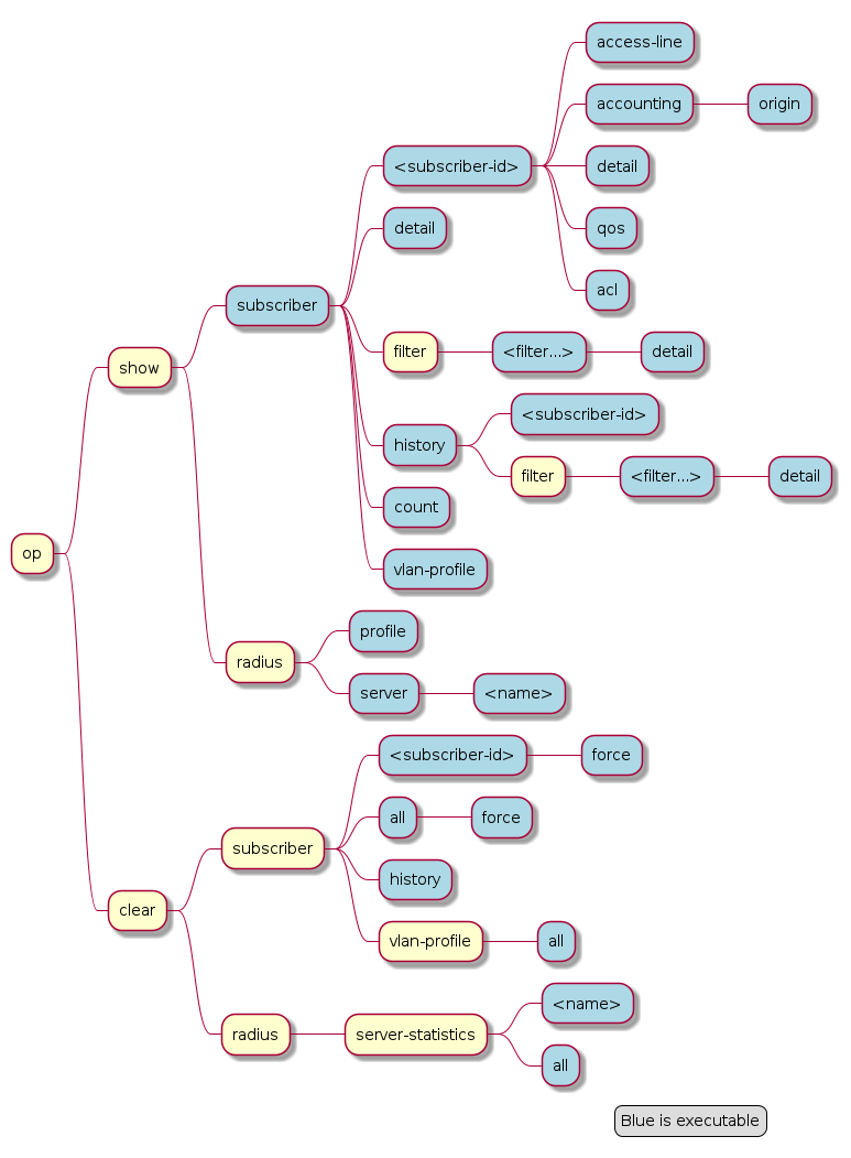
3.1.1. Subscribers
The term subscriber describes an access user or session from a higher level decoupled from underlying protocols like PPPoE or IPoE. Subscribers in RBFS can be managed locally or remote via RADIUS. Each subscriber is uniquely identified by a 64bit number called subscriber-id.
3.1.1.1. Subscriber States
A good starting point for troubleshooting subscriber services is to verify the status of the subscriber sessions. The state ESTABLISHED means that the session is fully operational.
supervisor@leaf1: op> show subscriber
Subscriber-Id          Interface        VLAN      Type   State
72339069014638600      ifp-0/0/1        1:1       PPPoE  ESTABLISHED
72339069014638601      ifp-0/0/1        1:2       PPPoE  ESTABLISHED
72339069014638602      ifp-0/0/1        1:3       PPPoE  ESTABLISHED
72339069014638603      ifp-0/0/3        2000:7    L2TP   ESTABLISHED
Alternative use show subscriber detail which shows further details like username, Agent-Remote-Id (aka Line-Id)
or Agent-Circuit-Id if screen width is large enough to print all those information.
The meaning of the subscriber state is shown in the following table and diagram.
| State | Description |
|---|---|
INIT |
Initial subscriber state. |
AUTHENTICATING |
Authenticate the subscriber using the configured method. |
ADDRESS ALLOCATION |
Allocate (RADIUS or pool) and validate (DAD) addresses. |
TUNNEL SETUP |
Setup tunnel resources (L2TP or L2X). |
IFL SETUP |
Create subscriber IFL with corresponding QoS resources. |
FULL |
Wait for subscriber to be in forwarding state. Inform underlying protocols (PPPoED or IPoED) to continue with session setup. |
ACCOUNTING |
Start subscriber accounting and wait for response. |
ESTABLISHED |
The subscriber becomes ESTABLISHED after response to RADIUS Accounting-Request-Start if RADIUS accounting is enabled otherwise immediately after FULL. |
TERMINATING |
The subscriber remains in this state until all resources are freed and accounting stopped. This means that subscriber remain in this state until response to RADIUS Accounting-Request-Stop if RADIUS accounting is enabled. |
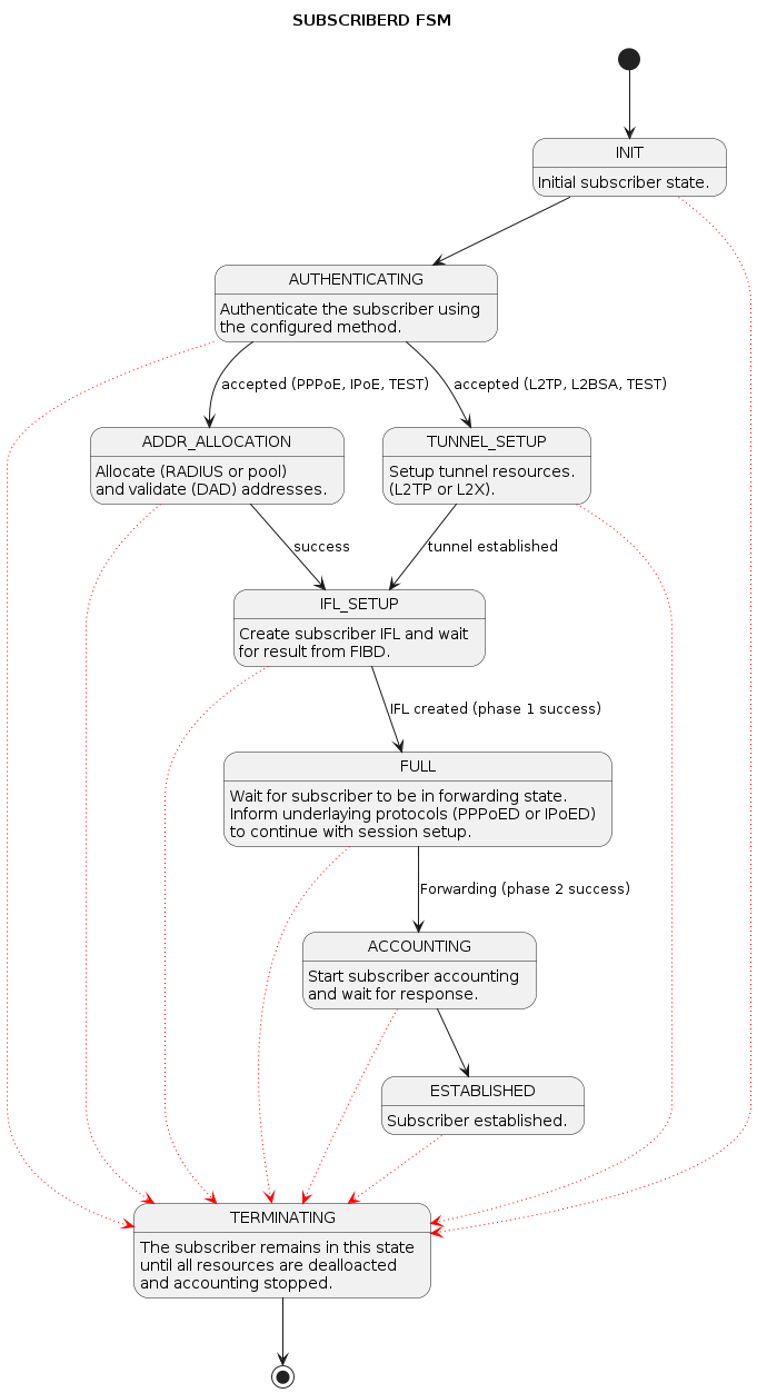
For each subscriber a set of commands is available showing detailed information.
supervisor@leaf1: op> show subscriber 72339069014638594
  <cr>
  access-line           Subscriber access line information
  accounting            Subscriber accounting information
  acl                   Subscriber ACL information (filter)
  detail                Detailed subscriber information
  qos                   Subscriber QoS information

user@switch: op> show subscriber 72339069014638594 detail
Subscriber-Id: 72339069014638594
    Type: PPPoE
    State: ESTABLISHED
    Created: Fri Sep 18 20:50:02 GMT +0000 2020
    Interface: ifl-0/0/1
    Outer VLAN: 128
    Inner VLAN: 7
    Client MAC: fe:08:e8:ea:1d:32
    Server MAC: 7a:52:4a:01:00:01
    IFL: ppp-0/0/1/72339069014638594
    Username: 1122334455#123456789#0001@t-online.de
    Agent-Remote-Id: DEU.DTAG.1337
    Agent-Circuit-Id: 0.0.0.0/0.0.0.0 eth 1337
    Access-Profile: access-profile1
    AAA-Profile: aaa-profile1
    Session-Timeout: 30000
    Idle-Timeout: 120
    IPv4:
        Instance: default
        Address: 198.51.100.116/255.255.255.255
        Address Active: True
        Primary DNS: 198.51.100.213
        Secondary DNS: 198.51.100.54
    IPv6:
        Instance: default
        RA Prefix: 2001:db8:0:400::/32
        RA Prefix Active: True
        Delegated Prefix (DHCPv6): 2001:db8:0:269::/56
        Delegated Prefix Active: False
        Primary DNS: 2001:db8:0:92::
        Secondary DNS: 2001:db8:0:174::
    Accounting:
        Session-Id: 72339069014638594:1600462202
        Start-Time: 2020-09-18T20:50:02.738306+0000
        Interims Interval: 30 seconds
3.1.1.2. Subscriber Termination Codes
The following command shows the reasons why subscribers are terminated for the last 24 hours and up to 4000 subscribers.
supervisor@leaf1: op> show subscriber history
Subscriber-Id          Timestamp                            Terminate Code
72339069014638594      Fri Oct 16 20:17:33 GMT +0000 2020   Accounting-Request-On Wait
72339069014638595      Fri Oct 16 20:32:19 GMT +0000 2020   PPPoE LCP Terminate Request Received
3.1.1.3. Subscriber Count
To view a summary of PPPoE, L2TP, IPoE, and L2BSA subscribers in the Setup, Established, and Terminating state, use the "show subscriber count" command. This command provides information per interface and a total summary based on subscriber type.
supervisor@leaf1: op> show subscriber count
                       Total        Setup        Established  Terminating
Summary                18000        0            18000        0
  PPPoE                18000        0            18000        0
  L2TP                 0            0            0            0
  IPoE                 0            0            0            0
  L2BSA                0            0            0            0
ifp-0/1/30             6000         0            6000         0
  PPPoE                6000         0            6000         0
  L2TP                 0            0            0            0
  IPoE                 0            0            0            0
  L2BSA                0            0            0            0
ifp-0/1/32             6000         0            6000         0
  PPPoE                6000         0            6000         0
  L2TP                 0            0            0            0
  IPoE                 0            0            0            0
  L2BSA                0            0            0            0
ifp-0/1/33             6000         0            6000         0
  PPPoE                6000         0            6000         0
  L2TP                 0            0            0            0
  IPoE                 0            0            0            0
  L2BSA                0            0            0            0
supervisor@leaf1: op>
3.1.2. RADIUS
3.1.2.1. RADIUS Profile
The following command shows the status of all RADIUS profiles.
supervisor@leaf1: op> show radius profile
RADIUS Profile: radius-default
    NAS-Identifier: BNG
    NAS-Port-Type: Ethernet
    Authentication:
        Algorithm: ROUND-ROBIN
        Server:
            radius-server-1
            radius-server-2
    Accounting:
        State: UP
        Stop on Reject: True
        Stop on Failure: True
        Backup: True
        Algorithm: ROUND-ROBIN
        Server:
            radius-server-1
            radius-server-2
This meaning of the accounting state is explained in the table below.
| Code | State | Description |
|---|---|---|
0x00 |
DISABLED |
Change profile accounting state from DISABLED to ACTIVE if at least one server referenced is found with accounting enabled. |
0x01 |
ACTIVE |
Server referenced by RADIUS profile but no response received |
0x02 |
STARTING |
Send accounting-on and wait for response. |
0x05 |
UP |
Change profile accounting state to UP if at least one referenced accounting server is UP. |
The profile state becomes immediately ACTIVE if at least one of the referenced accounting servers can be found in RADIUS server table with accounting enabled. Otherwise the profile keeps DISABLED.
If RADIUS Accounting-On is enabled, the profile state becomes STARTING before UP. It is not permitted to send any accounting request start, interim or stop related to a profile in this state. It is also not permitted to send authentication requests if accounting-on-wait is configured in addition. The state becomes UP if at least one server in the accounting server list is in a state UP or higher (UNREACHABLE, DOWN, TESTING, DEAD).
A new profile added which references existing used RADIUS servers must not trigger a RADIUS Accounting-On request if at least one of the referenced servers is in a state of UP or higher.
3.1.2.2. RADIUS Server
The following command shows the status of all RADIUS servers.
supervisor@leaf1: op> show radius server
RADIUS Server            Address          Authentication State Accounting State
radius-server-1          198.51.100.64    ACTIVE               UP
radius-server-2          198.51.100.163   ACTIVE               ACTIVE
radius-server-3          198.51.100.104   ACTIVE               ACTIVE
This meaning of those states is explained in the table and diagram below.
| Code | State | Description |
|---|---|---|
0x00 |
DISABLED |
RADIUS authentication (authentication state) or accounting (accounting state) is disabled or server not referenced by profile. |
0x01 |
ACTIVE |
Server referenced by RADIUS profile but no valid response received. |
0x02 |
STARTING |
This state is valid for accounting (accounting state) only during accounting-on is sending (wait for accounting-on response). |
0x03 |
STOPPING |
This state is valid for accounting (accounting state) only during accounting-off is sending (wait for accounting-off response). |
0x04 |
FAILED |
This state is valid for accounting (accounting state) only if accounting-on/off timeout occurs. |
0x05 |
UP |
Valid RADIUS response received |
0x06 |
UNREACHABLE |
No response received/timeout but server is still usable. |
0x07 |
DOWN |
Server is down but can be selected. |
0x08 |
TESTING |
Send a request to test if server is back again. The server will not be selected for another request in this state (use a single request to check if server is back again). |
0x09 |
DEAD |
Server is down and should not be selected. |
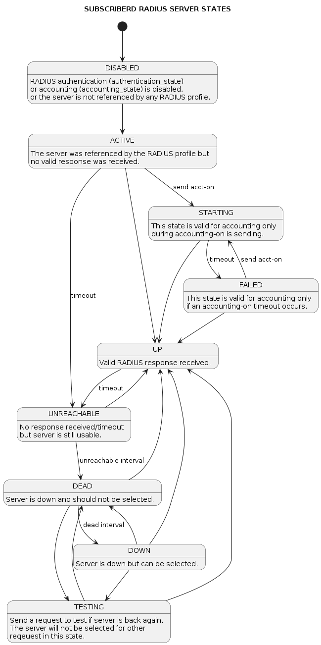
For each server dedicated detailed information are displayed with the following commands.
supervisor@leaf1: op> show radius server radius-server-1
RADIUS Server: radius-server-1
    Address: 198.51.100.64
    Source: 198.51.100.200
    Rate: 600 PPS
    Rate Tokens: 600
    Dropped: 0
    Authentication:
        State: ACTIVE
        State Changed: Fri Oct 16 20:17:27 GMT +0000 2020
        Port: 1812
        Retry: 3
        Timeout: 5
        Outstanding: 100
        Statistics:
            Request Sent: 0
            Request Retry: 0
            Request Timeout: 0
            Accept Received: 0
            Reject Received: 0
            Dropped: 0
    Accounting:
        State: UP
        State Changed: Fri Oct 16 20:18:27 GMT +0000 2020
        Port: 1813
        Retry: 10
        Timeout: 30
        Outstanding: 100
        Statistics:
            Request Sent: 1
            Request Retry: 2
            Request Timeout: 0
            Response Received: 1
            Dropped: 0
    CoA:
        Port: 3799
        Statistics:
            Request Received: 0
            Dropped: 0
3.2. PPPoE
The following commands are applicable for PPPoE sessions only.
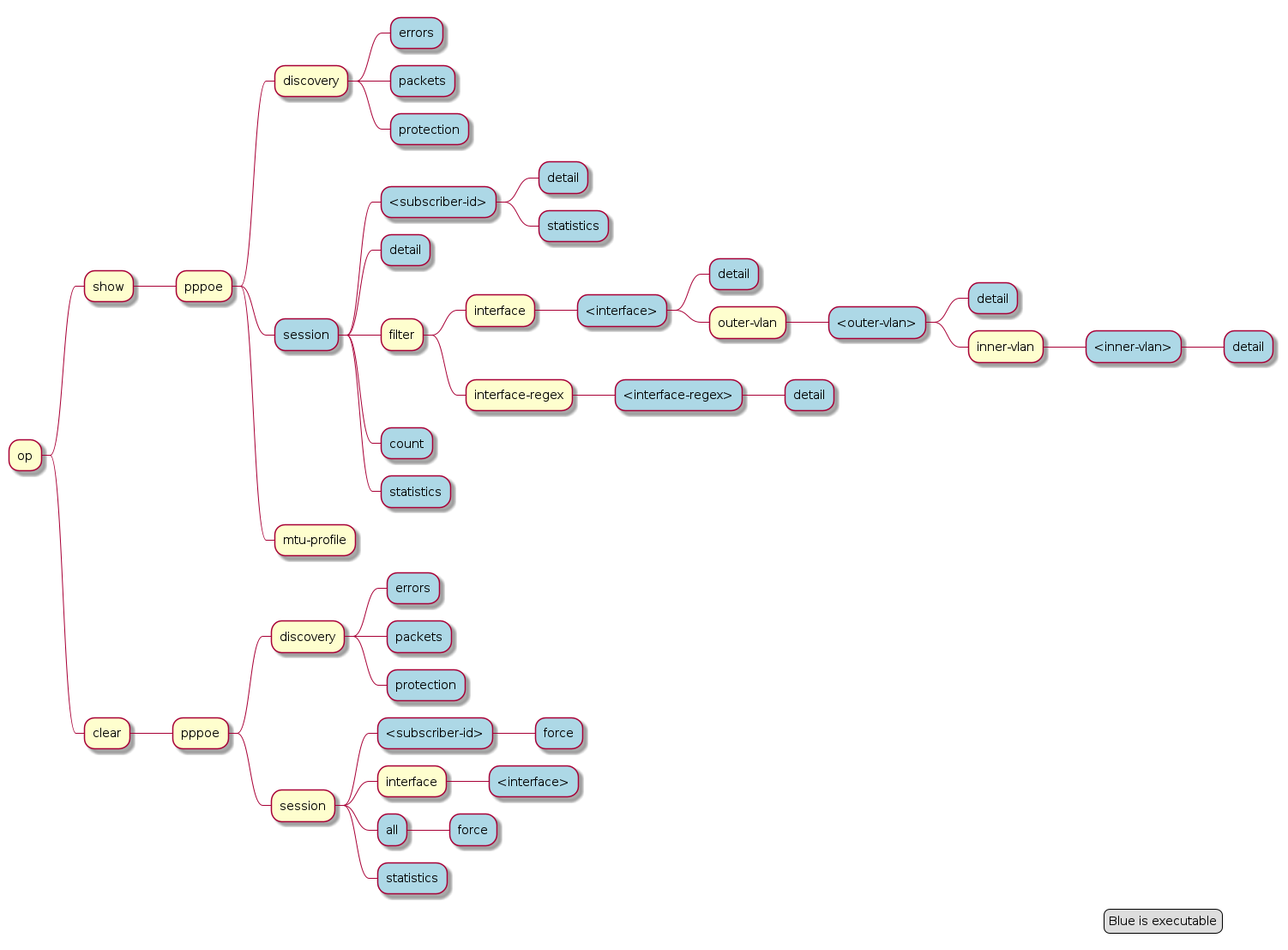
For PPPoE sessions the state should be ESTABLISHED if local terminated or TUNNELLED for L2TPv2 tunnelled sessions.
supervisor@rtbrick: op> show pppoe session
Subscriber-Id          Interface        VLAN      MAC               State
72339069014638604      ifp-0/0/1        1:1       00:04:0e:00:00:01 ESTABLISHED
72339069014638601      ifp-0/0/1        1:2       00:04:0e:00:00:02 ESTABLISHED
72339069014638602      ifp-0/0/1        1:3       00:04:0e:00:00:03 ESTABLISHED
72339069014638603      ifp-0/0/3        2000:7    52:54:00:57:c8:29 TUNNELLED
Alternative use show pppoe session detail which shows further details like username, Agent-Remote-Id (aka Line-Id) or Agent-Circuit-Id if screen
width is large enough to print all those information.
| State | Description |
|---|---|
LINKING |
PPP LCP setup. |
AUTHENTICATING |
PPP authentication (PAP or CHAP). |
NETWORKING |
PPP IPCP (IPv4) and IP6CP (IPv6) setup. |
ESTABLISHED |
The PPPoE session becomes established if at least one NCP (IPCP or IP6CP) is established (state OPEN). |
TUNNELLED |
This state indicates that a PPPoE session is tunnelled via L2TPv2. |
TERMINATING |
PPP session teardown. |
TERMINATED |
PPPoE session terminated. |
If PPPoE session remain in state TERMINATED, the subscriber state should be checked. Typically this happens if RADIUS Accounting-Request-Stop is still pending.
Further details per PPPoE session can be shown with the following commands.
supervisor@rtbrick: op> show pppoe session 72339069014638648
  <cr>
  detail                Detailed session information
  statistics            Protocol statistics
The detail command shows the states of the session and all sub-protocols with extensive information and negotiated parameters.
user@switch: op> show pppoe session 72339069014638648 detail
Subscriber-Id: 72339069014638648
    State: ESTABLISHED
    Uptime: Tue Nov 17 11:46:43 GMT +0000 2020 (0:00:21.979775)
    Interface: ifp-0/0/3
    Outer VLAN: 10
    Inner VLAN: 7
    Client MAC: 52:54:00:57:c8:29
    Server MAC: 7a:52:4a:c0:00:03
    Session-Id: 55
    Host-Unique: 00000001
    Agent-Remote-Id: DEU.RTBRICK.1
    Agent-Circuit-Id: 0.0.0.0/0.0.0.0 eth 1
    Access-Profile: pppoe-dual
    AAA-Profile: aaa-default
    PPP LCP:
        State: OPENED
        Negotiated Protocols: CHAP, IPCP, IP6CP
        Negotiated Parameters: MRU, AUTH, MAGIC
        Magic Number: 1079931229 Peer: 3432759752
        MRU: 1492 Peer: 1492
        MTU: 1492 Profile: __default_pppoe__
        Echo Interval: 30 seconds
    CHAP Authentication:
        State: COMPLETED
        Username: user1@rtbrick.com
    PPP IPCP:
        State: OPENED
        Instance: default
        IP Address: 198.51.100.200 Peer: 198.51.100.72
        Primary DNS: 198.51.100.88
        Secondary DNS: 198.51.100.54
    PPP IP6CP:
        State: OPENED
        Instance: default
        Interface Identifier: c5f6:1dbd:8cc1:bea9
        Peer Interface Identifier: 5054:00ff:fe57:c829
    IPv6:
        RA Interval: 60 seconds
        RA Prefix: 2001:db8:0:246::/32
        Delegated Prefix (DHCPv6): 2001:db8:0:9::/32 Assigned: True
        Primary DNS: 2001:db8:0:114::
        Secondary DNS: 2001:db8:0:115::
    Control Traffic Statistics:
        Ingress: 15 packets 1059 bytes
        Egress: 16 packets 1475 bytes
Session statistics are available global and per session.
supervisor@rtbrick: op> show pppoe session statistics
supervisor@rtbrick: op> show pppoe session 72339069014638601 statistics
The PPPoE discovery statistics are helpful if session setup fails in initial PPPoE tunnel setup before actual PPP negotiation is starting.
supervisor@rtbrick: op> show pppoe discovery packets
Packet           Received         Sent
PADI             17               0
PADO             0                17
PADR             17               0
PADS             0                17
PADT             1                13

supervisor@rtbrick: op> show pppoe discovery errors
PADI Drop No Config            : 0
PADI Drop Session Protection   : 0
PADI Drop Session Limit        : 0
PADI Drop Dup Session          : 0
PADI Drop Interface Down       : 0
PADR Drop No Config            : 0
PADR Drop Wrong MAC            : 0
PADR Drop Interface Down       : 0
PADR Drop Session Limit        : 0
PADR Drop Session Protection   : 0
PADR Drop Bad Cookie           : 0
PADR Drop Bad Session          : 0
PADR Drop Dup Session          : 0
PADR Drop No mapping Id        : 0
PADT Drop No Session           : 0
PADT Drop Wrong MAC            : 0
PADX Interface Get Failure     : 0
If PPPoE session protection is enabled in access configuration profile,
short lived or failed sessions will be logged in the PPPoE session protection
table (local.pppoe.session.protection).
Every session not established for at least 60 seconds per default is considered as failed or short lived session. This will block new sessions on this IFP and VLAN’s for one second per default which increase exponential with any further failed session until the max time of per default 300 seconds is reached. The interval is reset after 900 seconds without failed sessions.
The PPPoE session protection table include also last subscriber-id and terminate code which indicates the reason for session failures.
supervisor@rtbrick: op> show pppoe discovery protection
Interface        VLAN      Status  Attempts   Last Terminate Code
ifp-0/0/1        1:1       OK      1          PPPoE LCP Terminate Request Received
ifp-0/0/1        1:2       OK      1          PPPoE LCP Terminate Request Received
ifp-0/0/1        1:3       OK      1          PPPoE LCP Terminate Request Received
If status OK indicates that new session are accepted where BLOCKED means that sessions will be rejected.
3.3. L2TP
The following commands are applicable for L2TP only.
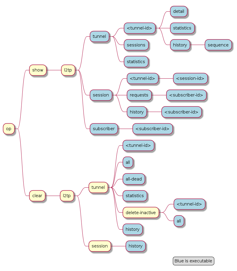
For L2TPv2 tunnelled PPPoE sessions the global unique subscriber-id can be used to get information about the L2TP session.
supervisor@rtbrick: op> show l2tp subscriber 72339069014638621
Subscriber-Id: 72339069014638621
    State: ESTABLISHED
    Local TID: 45880
    Local SID: 39503
    Peer TID: 1
    Peer SID: 1
    Call Serial Number: 10
    TX Speed: 10007000 bps
    RX Speed: 1007000 bps
    CSUN: disabled
The following command gives a good overview over the corresponding tunnels.
supervisor@leaf1: op> show l2tp tunnel sessions
Role Local TID Peer TID State        Preference Sessions Established Peer Name
LAC       2022        1 ESTABLISHED       10000        1           1 LNS3
LAC       3274        1 ESTABLISHED       10000        1           1 LNS8
LAC      14690        1 ESTABLISHED       10000        1           1 LNS6
LAC      29489        1 ESTABLISHED       10000        1           1 LNS9
LAC      33323        1 ESTABLISHED       10000        1           1 LNS4
LAC      35657        1 ESTABLISHED       10000        1           1 LNS10
LAC      37975        1 ESTABLISHED       10000        1           1 LNS1
LAC      45880        1 ESTABLISHED       10000        1           1 LNS7
LAC      46559        1 ESTABLISHED       10000        1           1 LNS2
LAC      58154        1 ESTABLISHED       10000        1           1 LNS5
Detailed information per tunnel are available via show l2tp tunnel <TID> detail.
L2TP tunnel statistics are available global and per tunnel.
supervisor@leaf1: op> show l2tp tunnel statistics
supervisor@leaf1: op> show l2tp tunnel 37975 statistics
3.3.1. L2TP Result and Disconnect Codes
The received result (RFC2661) and disconnect (RFC3145) code and message from CDN and StopCCN will be stored similar to the subscriber terminate history table for 24 hours and up to 1000 records.
supervisor@leaf1: op> show l2tp tunnel history
Sequence Local TID Peer TID Timestamp                            Terminate Code
       1     34209        0 Wed Jul 28 13:02:35 GMT +0000 2021   Admin Request
       2     39860        1 Wed Jul 28 13:02:35 GMT +0000 2021   Admin Request
       3     39860        2 Wed Jul 28 13:02:54 GMT +0000 2021   Admin Request
       4     39860        3 Wed Jul 28 13:04:29 GMT +0000 2021   StopCCN Received (Requester is being shut down)
       5     39860        1 Wed Jul 28 13:06:19 GMT +0000 2021   StopCCN Received (Requester is being shut down)

supervisor@leaf1: op> show l2tp tunnel history 4
Local TID: 39860 Peer TID: 3
    Terminate Code: StopCCN Received
    Timestamp: Wed Jul 28 13:04:29 GMT +0000 2021
    Local Address: 198.51.100.102
    Peer Address: 198.51.100.133
    Peer Name: LNS1
    Tunnel-Client-Auth-ID: BNG
    Tunnel-Server-Auth-ID: LNS1
    Result Code: Requester is being shut down

supervisor@leaf1: op> show l2tp session history
Subscriber-Id          Local TID Local SID Terminate Code
72339069014638614          39860      5597 Clear Session
72339069014638615          39860      5208 Clear Session
72339069014638623          39860     29626 Clear Session
72339069014638624          39860     42480 L2TP Tunnel Down
72339069014638625          39860     34417 L2TP Tunnel Down
72339069014638626          39860     20229 L2TP Tunnel Down
The show subscriber history <subscriber-id> command will
also return L2TP details if found for the corresponding subscriber.
supervisor@leaf1: op> show subscriber history 72339069014638703
Subscriber-Id: 72339069014638703
    Terminate Code: L2TP CDN Request
    Timestamp: Wed Jul 28 13:06:18 GMT +0000 2021
    Interface: ifl-0/0/1
    Outer VLAN: 1000
    Inner VLAN: 2002
    Client MAC: 02:00:00:00:00:04
    Username: blaster@l2tp.de
    Agent-Remote-Id: DEU.RTBRICK.2
    Agent-Circuit-Id: 0.0.0.0/0.0.0.0 eth 0:2
    Accounting-Session-Id: 72339069014638703:1627477569
    L2TP Disconnect Cause:
        Code: Normal disconnection (LCP terminate-request)
        Protocol: 0
        Direction: Peer
        Message: N/A
3.4. IPoE
The following commands are applicable for IPoE subscribers only.
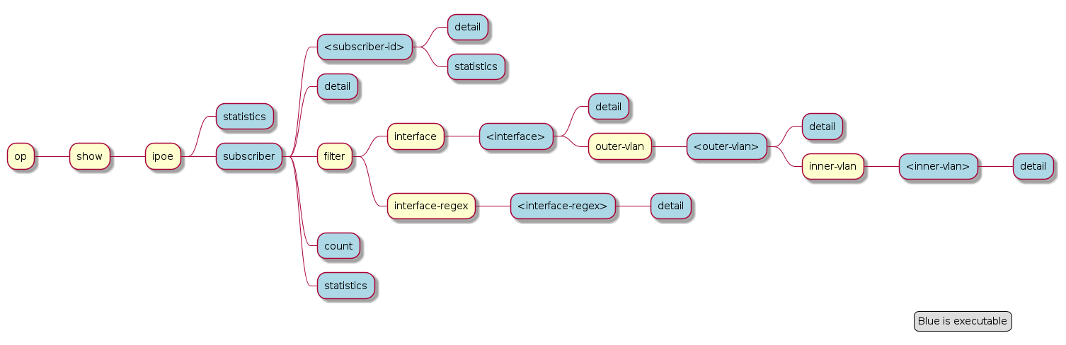
supervisor@leaf1: op> show ipoe subscriber detail
Subscriber-Id          Interface        VLAN      MAC               State          DHCPv4     DHCPv6
216454257090494465     ifl-0/0/1     8:1       02:00:00:00:00:01 ESTABLISHED    Bound      Bound
216454257090494466     ifl-0/0/1     8:2       02:00:00:00:00:02 ESTABLISHED    Bound      Bound
216454257090494467     ifl-0/0/1     8:3       02:00:00:00:00:03 ESTABLISHED    Bound      Bound
216454257090494468     ifl-0/0/1     8:4       02:00:00:00:00:04 ESTABLISHED    Bound      Bound
Further details per subscriber can be shown with the following command.
supervisor@leaf1: op> show ipoe subscriber 216454257090494465 detail
Subscriber-Id: 216454257090494465
    State: ESTABLISHED
    Uptime: Mon Jun 14 15:46:15 GMT +0000 2021 (0:02:19.421591)
    Interface: ifl-0/0/1
    Outer VLAN: 8
    Inner VLAN: 1
    Client MAC: 02:00:00:00:00:01
    Gateway Interface: lo-0/0/0/1
    Gateway Instance: default
    Gateway IPv4: 198.51.100.200/255.255.255.255
    Gateway MAC: 7a:52:4a:c0:00:01
    Agent-Remote-Id: DEU.RTBRICK.1
    Agent-Circuit-Id: 0.0.0.0/0.0.0.0 eth 0:1
    DHCPv4:
        Mode: Server
        State: Bound
        Address: 198.51.100.202/255.255.255.255
        Lease Created: Mon Jun 14 15:46:15 GMT +0000 2021 (0:02:19.427443)
        Lease Time: 300 seconds
        Lease Expire: 161 seconds
    DHCPv6:
        Mode: Server
        State: Bound
        Client DUID: 00030001020000000001
        Server DUID: 0003001b78524afffec00001
        IA_NA:
            Address: 2001:db8:0:96
            IAID: 1181407340
            Active: True
        IA_PD:
            Prefix: 2001:db8:0:333/32
            IAID: 4095128883
            Active: True
        Lease Created: Mon Jun 14 15:46:15 GMT +0000 2021 (0:02:19.428676)
        Lease Time (Lifetime): 14400 seconds
        Lease Expire: 14261 seconds
        Preferred Lifetime: 1800 seconds
3.5. Local Address Pools
|
|
Rather than using recommended IP addresses for technical documents, the document shows actual IP pool ranges. |
The usage of local address pools can be monitored using the show subscriber pool commands as shown below.
supervisor@switch: op> show subscriber pool summary
Pool Name                        AFI  Usage           Range
pool-A                           IPv4 256/256         10.0.1.0 - 10.0.1.255
pool-B                           IPv4 2/256           10.0.2.0 - 10.0.2.255
pool-C                           IPv4 0/256           10.0.3.0 - 10.0.3.255
pool-D                           IPv4 0/256           10.0.4.0 - 10.0.4.255

supervisor@switch: op> show subscriber pool ipv4 pool-A
Pool Name: pool-A
    AFI: IPv4
    Usage: 256/256
    Range: 10.0.1.0 - 10.0.1.255
    Next: pool-B

supervisor@switch: op> show subscriber pool ipv4 pool-B
Pool Name: pool-B
    AFI: IPv4
    Usage: 2/256
    Range: 10.0.2.0 - 10.0.2.255
    Next: pool-C

supervisor@switch: op> show subscriber pool ipv4 pool-B allocation
Subscriber-Id          Timestamp                            Address/Prefix
72339069014638598      Wed Sep 15 09:02:15 GMT +0000 2021   10.0.2.0
72339069014638602      Wed Sep 15 09:02:15 GMT +0000 2021   10.0.2.1
4. Supported Standards
|
|
RFC and draft compliance are partial except as specified. |
4.1. PPPoE
-
RFC 1516
-
RFC 1661 (partly)
-
RFC 1332 (partly)
-
RFC 5072 (partly)
-
RFC 1334 (partly)
4.2. RADIUS
-
RFC 2865 (partly)
-
RFC 3162 (partly)
-
RFC 2866 (partly)
-
RFC 4372 (partly)
-
RFC 2869 (partly)
4.3. DHCPv4
-
RFC 951 (partly)
-
RFC 1542 (partly)
-
RFC 2131 (partly)
-
RFC 2132 (partly)
-
RFC 3046 (partly)
4.4. DHCPv6
-
RFC 8415 (partly)
4.5. Access Line Information
The access line identification and characterization information are defined in the Broadband Forum (BBF) formerly known DSL Forum attributes including Agent-Remote-Id and Agent-Circuit-Id.
See the following references for more information about access line attributes.
-
RFC 4679 DSL Forum Vendor-Specific RADIUS Attributes
-
RFC 6320 ANCP (partly)
-
Broadband Forum TR-101 (partly)
-
draft-lihawi-ancp-protocol-access-extension-04 (partly)
4.6. L2TPv2
|
|
RFC and draft compliance are partial except as specified. |
4.6.1. RFC 2661 - Layer Two Tunneling Protocol (L2TPv2)
RFC compliant L2TPv2 Access Concentrator (LAC) with the following protocol limitations:
-
No support for LNS initiated outbound calls (OCRQ, OCRP and OCCN)
-
No support for WAN-Error-Notify (WEN) Messages send by LAC to LNS
-
No support for Set-Link-Info (SLI) Messages send by LNS to LAC
-
No support for L2TP over IPv6
-
No support for L2TP offset values other than 0.
4.6.2. RFC 5515 - L2TP Access Line Information AVP Extensions
-
Support for access line AVP send (LAC) and received (LNS) as part of the L2TP Incoming-Call- Request (ICRQ) message.
-
Response to Connect-Speed-Update-Request (CSURQ) L2TP messages is currently not supported.
4.6.3. RFC 2868 - RADIUS Attributes for Tunnel Protocol Support
RADIUS support for L2TP with the following limitations:
-
No support of FQDN format for IP addresses
-
No support Tunnel-Medium-Type other than IPv4
4.6.4. RFC 3145 - L2TP Disconnect Cause Information
Send meaningful disconnect cause information to LNS and display received disconnect cause information for tunnels and sessions.
4.6.5. Supported Hardware
You can find more detailed information about what RtBrick features are supported on each hardware platform, see the Platform Guide.
©Copyright 2024 RtBrick, Inc. All rights reserved. The information contained herein is subject to change without notice. The trademarks, logos and service marks ("Marks") displayed in this documentation are the property of RtBrick in the United States and other countries. Use of the Marks are subject to RtBrick’s Term of Use Policy, available at https://www.rtbrick.com/privacy. Use of marks belonging to other parties is for informational purposes only.